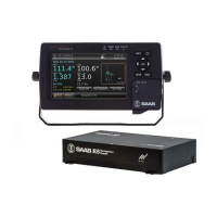
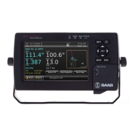
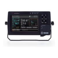
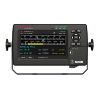
R5 SOLID AIS System
INSTALLATION
7000 118-200, C2 Page 12
3.2 Installation Cables
The following cables are needed to install the R5 SOLID.
R5 Signal Cable, DSUB-Open
Type: Shielded Twisted Pair x 0.33 mm
2
Length: 2 m
Connector: 26-pole H.D.D-SUB (female)
Marking: 7000 118-078, A
R5 Power Cable
Type: Unshielded 4 wire cable x 1.3 mm
2
Length: 2 m
Connector: ConXall Mini-Con-X 6382-4SG-311 (female)
Marking: 7000 118-077, A
R5 SOLID VHF Antenna Cable
Type and length: See section 3.5.2 VHF Cabling
Connector: BNC (Male)
R5 SOLID GPS Antenna Cable
The standard GPS antenna MA-700 for the R5 SOLID transponder system is
prewired with an antenna cable. For other GPS antennas an extern GPS
antenna cable is needed.
Type and Length: See section 3.6.2 GPS Cabling
Connector: TNC (Male)
3.3 Installation procedure
When installing the R5 SOLID, it is recommended to follow the steps described in this
Installation Manual. Details of the installation procedure can be found in the coming
sections of the Installation Manual.
Recommended installation steps:
1. Mount the R5 SOLID at conning station
2. Mount the alarm relay unit
3. Mount the VHF antenna
4. Mount the GPS antenna
5. Connect all external systems and sensors to the R5 SOLID
6. Power up the system
7. Set configuration parameters
8. Perform system functional check