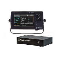
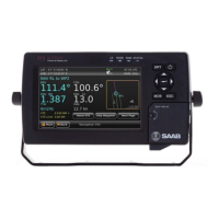
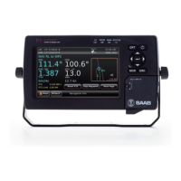
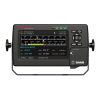
R5 SOLID AIS System
THE AUTOMATIC IDENTIFICATION SYSTEM
7000 118-200, C2 Page 5
TABLE OF CONTENTS
1 The Automatic Identification System ............................................. 8
2 System Overview.............................................................................. 9
2.1 Product Description................................................................................................ 9
2.2 Main features......................................................................................................... 10
3 Installation ...................................................................................... 11
3.1 Unpacking the Equipment .................................................................................... 11
3.2 Installation Cables ................................................................................................ 12
3.3 Installation procedure .......................................................................................... 12
3.4 Mount the R5 SOLID ............................................................................................. 13
3.5 Mount the R5 SOLID Transponder’s VHF antenna ............................................. 17
3.6 Mount the R5 SOLID GPS Antenna ...................................................................... 19
3.7 Electrical Installation ............................................................................................ 21
3.8 System Configuration ........................................................................................... 25
4 Operation......................................................................................... 27
4.1 System Mode......................................................................................................... 27
4.2 LED’s and Controls............................................................................................... 27
4.3 Main Menu – Tree View ......................................................................................... 30
4.4 Configuration Parameters .................................................................................... 31
4.5 Alarm and Alert Pop-ups ...................................................................................... 40
4.6 Status Bar .............................................................................................................. 41
4.7 Status Icons .......................................................................................................... 41
4.8 View Remote Ship Information ............................................................................ 42
4.9 View Plot of Targets.............................................................................................. 43
4.10 View Transmitted Own Ship Information ............................................................ 43
4.11 Enter and Read Voyage Related Information ...................................................... 44
4.12 Handling Safety Related Messages (SRM) and Text Messages ......................... 44
4.13 Send Persons On Board ....................................................................................... 46
4.14 Long Range Interrogations .................................................................................. 46
4.15 Inland ETA and RTA ............................................................................................. 47
4.16 Inland Water Levels .............................................................................................. 48
4.17 Regional Areas...................................................................................................... 48
4.18 Alarms ................................................................................................................... 48
4.19 Status List ............................................................................................................. 49
4.20 Non Functional Time ............................................................................................ 49