Removal and Installation of Engine and Propulsion/Vibration/Steering/Charge Pump Assembly
5-104
4. Removal and Installation of Engine and
Propulsion/Vibration/Steering/Charge Pump Assembly
4-1. Removal of engine and propulsion/vibrator/steering/charge pump
assembly
Disconnect the battery negative (–) cable.
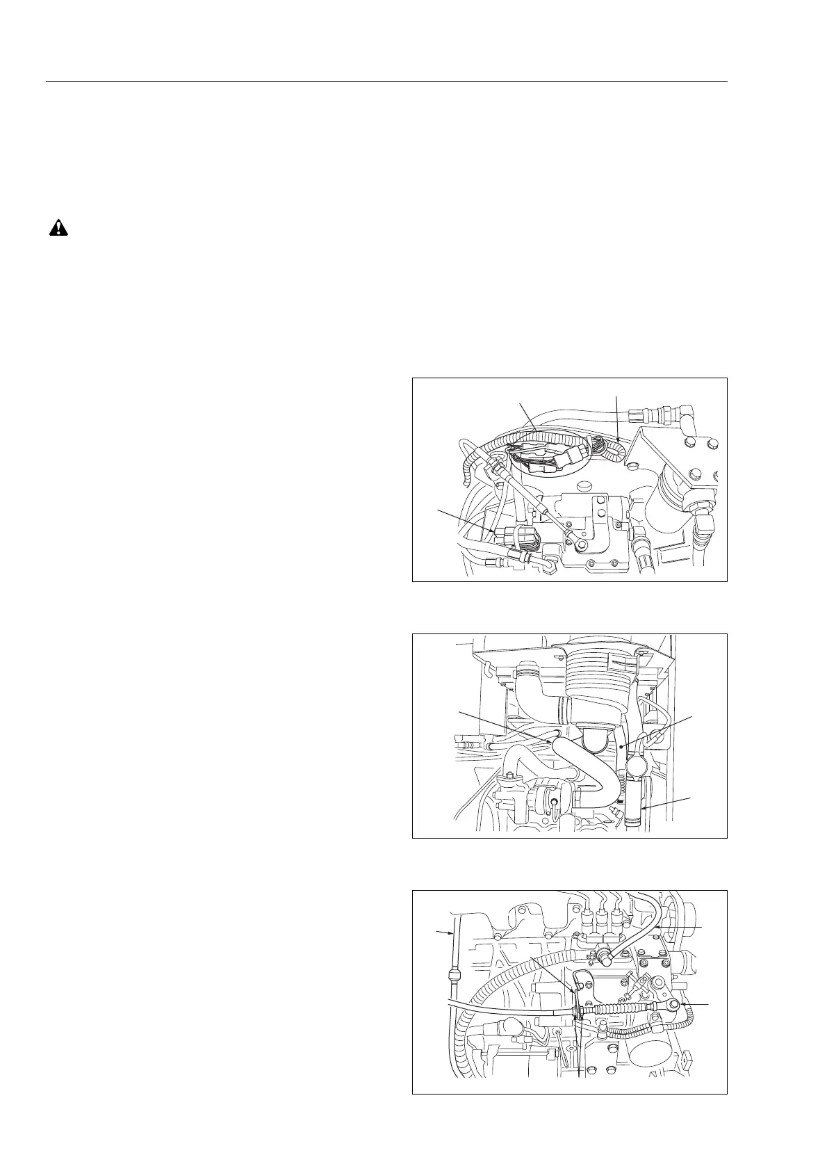
2. Electric wiring
1) Disconnect connector (1), harness (2) and
propulsion pump solenoid valve wire
connector (3). Put the harness at a location
which does not hinder the work.
2) Disconnect wires at the engine that carry
oil pressure sensor, thermo sensor,
tachometer sensor and glow plugs.
3) Disconnect wires at the alternator and
starter.
* See procedures under “Electric wiring of
alternator”, page 5-101 and “Electric
wiring of starter”, page 5-102.
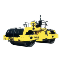
3. Air cleaner
Disconnect air cleaner intake hose (4).
4. Radiator hose
1) Drain the coolant from the radiator.
2) Remove upper hose (5) and lower hose
(6).
1. Removal of engine hood
1) Remove the damper inside the hood.
2) Lift the hood and remove the hinge and
anti-fall arm. Take off the hood assembly.
3) Remove the front frame left side cover.
5. Throttle cable
Disconnect throttle cable (7) from the
governor lever. Unscrew nut (8) and detach
throttle cable at yoke (9).
6. Fuel hose
Disconnect fuel hoses (10) and (11).