2-030
Description and Operation of Hydraulic System
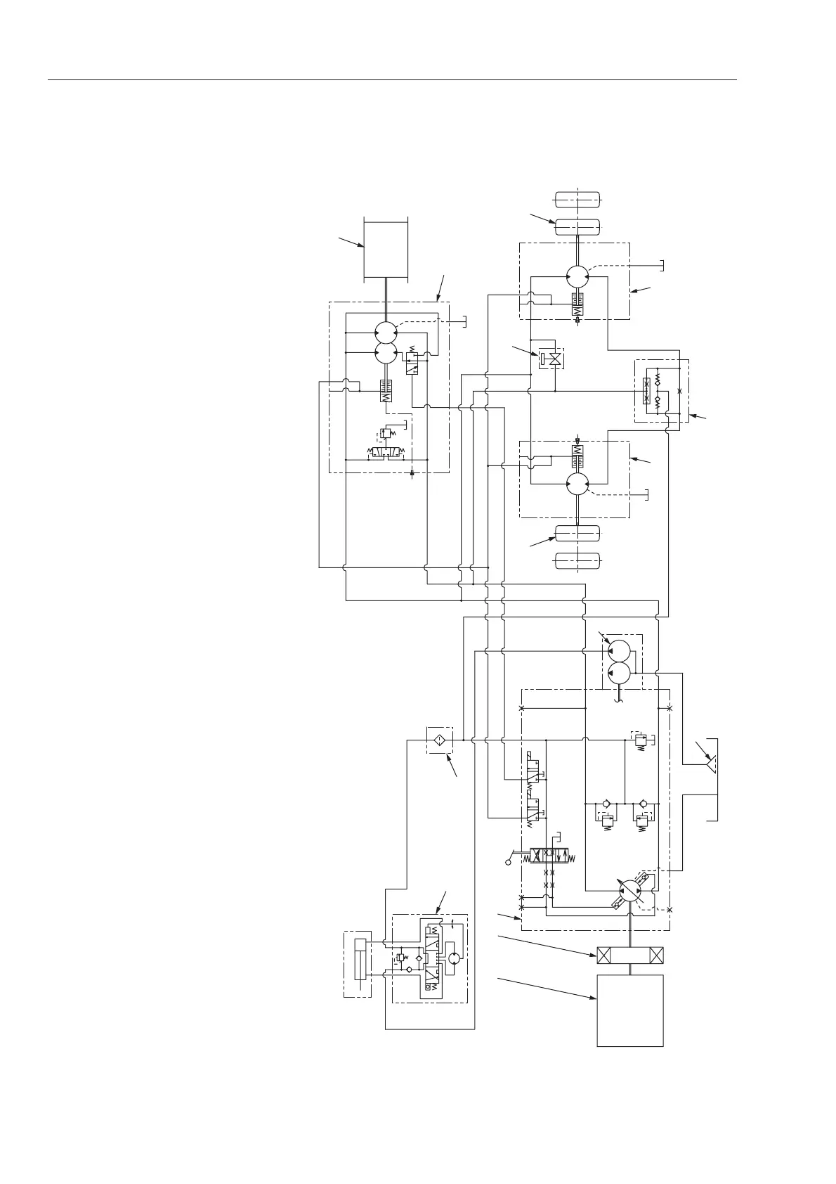
2-2-10. Propulsion circuit diagram (TW352, TW502)
1. Engine
2. Coupling
3. Propulsion pump
a. Control valve
b. Servo piston
c. Multi-function valve
d. Charge relief valve
e. Brake release solenoid valve
f. Speed selector solenoid valve
4. Steering/charge pump
5.
Front propulsion motor assembly
(cam motor)
g. Speed selector valve
h. Spring-applied hydraulically
released brake
i. Flushing valve
j. Low pressure relief valve
k. Brake release bolt
6. Front drum
7. Left-hand rear propulsion motor
assembly (cam motor)
8. Left-hand rear wheel
9. Right-hand rear propulsion
motor assembly (cam motor)
10. Right-hand rear wheel
11. Steering valve (Orbitrol)
m. Pressure relief valve
12. Line filter
13. Differential lock valve assembly
14. Bypass valve
15. Suction filter
 Loading...