2-031
Description and Operation of Hydraulic System
2-2-11. Description and operation of propulsion system
*
See the hydraulic circuit diagrams, pages 2-029 and 2-030.
Description of propulsion system
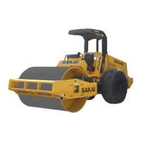
SW352, SW502
・Comprises propulsion pump (3), front propulsion motor (cam motor) (6), front drum (7), rear
propulsion motor (cam motor) (8) and rear drum (9). Brake release solenoid valve (e) and speed
selector valve (f) are built into the propulsion pump.
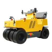
TW352, TW502
・Consists of propulsion pump (3), front propulsion motor (cam motor) (5), front drum (6), left-hand
rear propulsion motor (cam motor) (7), right-hand rear propulsion motor (cam motor) (9), left-hand
rear wheels (8) and right-hand rear wheels (10). Brake release solenoid valve (e) and speed
selector valve (f) are built into the propulsion pump.
Fundamental function of propulsion pump and propulsion motor
Propulsion pump
・A piston pump shifts speed and selects forward travel, neutral drive and backing by varying the
angular position of swashplate, and thus varying the piston stroke.
Front propulsion motor
・A radial piston motor (cam motor) selects speed by operating the speed selector valve built in the
motor. Feeding the pump flow to four of eight pistons offers ‘Low speed range’, while supplying to
two pistons selects ‘High speed’.
Rear propulsion motor
・The rear propulsion motor (SW352, TW352, SW502, TW502) uses a fixed displacement radial
piston motor (cam motor). Choice of two speeds in the front motor varies the amount of oil flowing
into the rear motor.
 Loading...