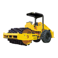
Font propulsion motor (cam motor fitted
with speed selector valve)
Operation
★
It is assumed that oil is fed into port A
of the motor.
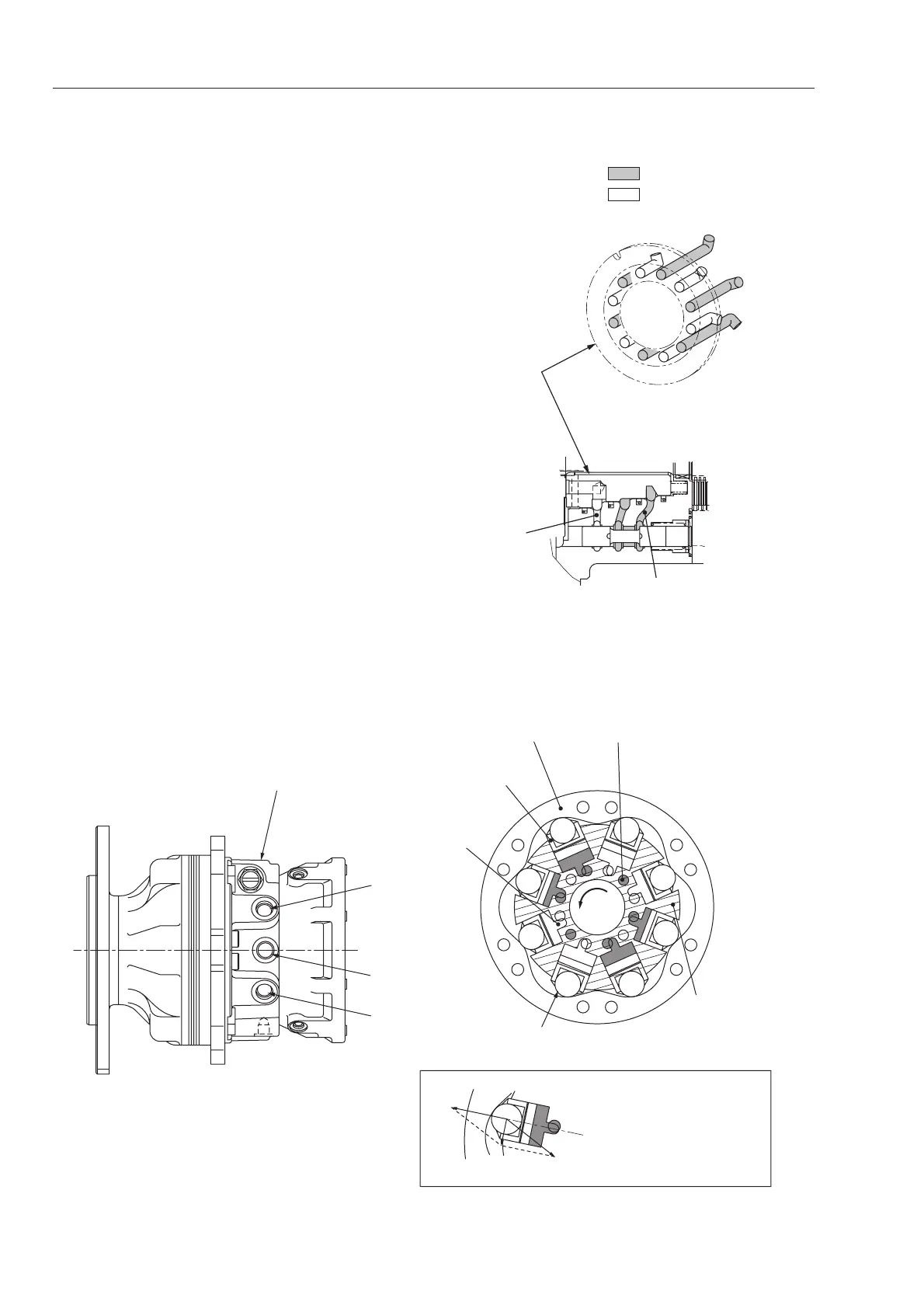
Selection of low speed
★ Spool operating pressure: lower than 0.2
MPa (2 kgf/cm
2
)
・Pump flow into port A of end cap (5) is
distributed, from two ports of speed selector
valve (12), into six ports of distributor (11).
★ Remaining six ports act as exhaust ports.
・Pistons (3) moving together with rollers (15)
along the cam profiles make cylinder block
(10) create a rotary force. This force is
conveyed to outpu flange (1) spline-fitted to
cylinder block (10).
・At the same time, pistons (3) leading to
exhaust port (port B) move along the cam
profile and toward the center of cylinder
block (10) to exhaust oil from port B.
★ If pump flow is fed to port B, output flange
(1) spins in the opposite direction.
 Loading...