2-026
Description and Operation of Hydraulic System
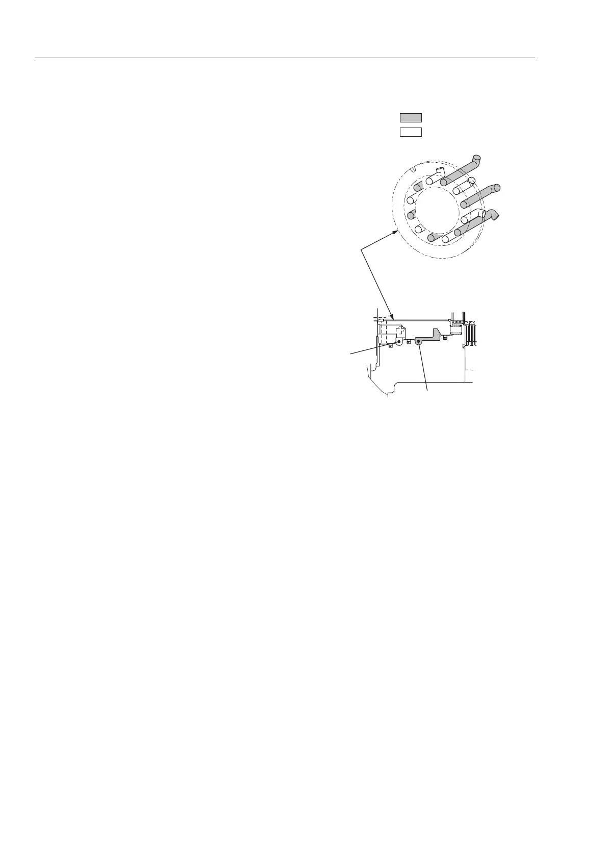
Rear propulsion motor (cam motor with
speed selector valve not fitted)
Operation
★
It is assumed oil is fed into port A of
motor.
・Pump flow into port A of end cap (5) is
distributed to six ports of distributor (11)
which lead to port A.
★ The remaining six ports act as exhaust
ports.
・If six ports of cylinder block (10) lead to six
ports of distributor (11), high pressure-oil
moves pistons outward.
・Because pistons (3) move along the cam
profiles together with rollers (15), rotary
force is generated in cylinder block (10).
This rotary force is transmitted to output
flange (1) spline-fitted to cylinder block (10).
Output flange (1) is driven.
・Simultaneously, pistons (3) leading to the
exhaust port (port B) move along the cam
profiles and, at the same time, outward to
exhaust oil from port A.
★ If pump flow is fed to port B, output flange
(1) turns in the reverse direction.
 Loading...