EB 5579 EN 131
Electrical connection
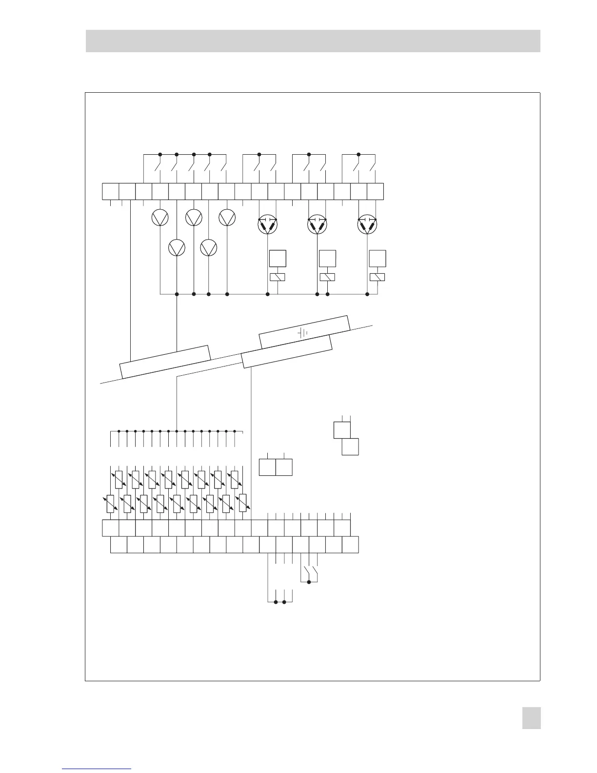
Fig. 16 · Wiring diagram
BA12
BA13
UP Ein/Aus
UP Drehzahl
Pumpenmanagement - COM
Gerätebus
Gerätebus
COM BA12, BA13
Y COM
Y1
Y2
Y3
0...10V
0...10V
0...10V
16
18
20
22
15
17
19
21
23
24
26
28
30
17
19
25
27
+ WMZ/Bed
Fühler COM
29
28
27
+ Betriebsspannung
- für TROVIS 5570*
1
- (20 mA/10 V)*
2
Zählerbus*
1
Zählerbus*
1
2
4
6
8
1
3
5
7
9
10
12
14
11
13
L1
L1
_
+
_
+
L1
N
L1
UP1
UP3
UP2
SLP
ZP
RK1_3-Pkt
RK2_3-Pkt
RK1_2-Pkt
RK2_2-Pkt
AF1
AF2
SF1
SF2
RF1
RF2
VF1
VF2
RF3
VF3
VF4
RüF1
RüF3
RüF2
FG1
FG2
SF3/FG3
BE1
BE2
BE3
BE4
BE5
BE6
BE7
BE8
BE9
BE10
BE11
BE12
BE13
BE14
BE15
BE16
BE17
38
39
40
41
41
44
_
+
L1
RK3_3-Pkt
RK3_2-Pkt
47
42
43
44
45
46
47
31
32
33
34
35
36
37
BA1
BA2
BA3
BA4
BA5
BA6
BA7
BA8
BA9
BA10
BA11
N
G
N
D
Caution!
Never connect terminals 18 (ground of sensor), 19 (ground of 0 to 10 V/0 to 20 mA) and 20 (ground of 0 to 10 V outputs)!
*
1)
If the controller is equipped with a meter bus module, the TROVIS 5570 Room Panel cannot be supplied by the
controller!
*
2)
To apply a 20 mA signal, a 50
Ω
resistor is required between terminals 17 and 19!