Connecting the sensors
Cables with a minimum cross-section of 2 x 0.5 mm² can be connected to the terminals at
the back panel of the housing.
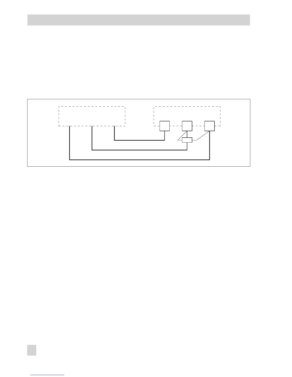
Connecting the water flowmeter (order no. 1400-9246)
A power supply unit and a 4.7 k
Ω
resistor are required for the water flowmeter to function.
Connecting the actuators
4
0 to 10 V outputs:
Use cables with a minimum cross-section of 2 x 0.5 mm².
4
Three-step or on/off outputs:
Connect cables with at least 1.5 mm² suitable for damp locations to the terminals of the
controller output. The direction of travel needs to be checked at start-up.
Connecting the pumps
Connect all cables with at least 1.5 mm² to the terminals of the controller as illustrated in the
wiring diagram.
Legend for wiring diagram (page 131):
AF Outdoor sensor RüF Return flow sensor
BA Binary output SF Storage tank sensor
BE Binary input SLP Storage tank charging pump
FG Potentiometer UP Circulation pump
RF Room sensor VF Flow sensor
Rk Control circuit WMZ Heat meter
132 EB 5579 EN
Electrical connection
4.7 kΩ
2117
TROVIS 5579
20
brown/
black
greenwhite
Water flowmeter