PY Manual Copyright © 2006 SANYO DENKI AMERICA, Inc.
38
CNA, CND and CNB Connectors
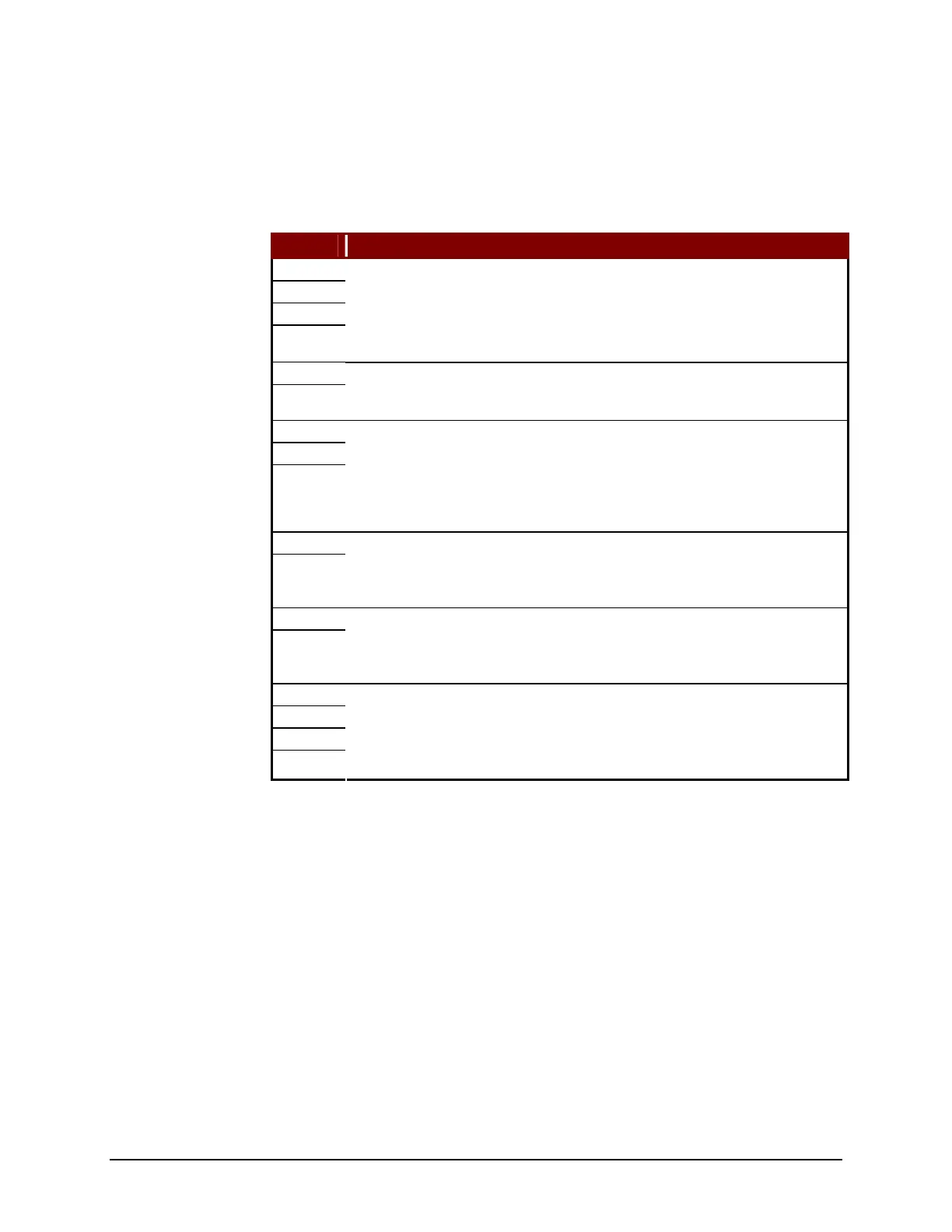
Table 11: CNA, CND, and CNB Connector Pin Assignments
Symbol Explanation
R
S
T
W
Bus circuit power input. Single/Three-phase 200-230Vac (+10%, -15%) and
grounding terminal. This is only the high power input for the amplifier.
Control power for the amplifier is supplied on the “r” and “t” terminals. For
single-phase connection, do not connect to the “S” terminal.
r
t
Control circuit power input terminals. Single-phase 200-230Vac (+10%,
-15%). This is the only control power input for the amplifier. The bus power
(high power) for the amplifier is supplied on the “R”, “S”, and “T” terminals.
COM
Y
P
Regeneration Resistor power connections. When an external regeneration
resistor is not used, the internal resistor is connected to “X” and “COM”
(PY0 Drive) and “X” and “P” (PY2 Drive). When an external regeneration
resistor is used, the internal resistor must be disconnected and the external
resistor(s) are connected between “COM” and “Y” (PY0 Drive) and “P” and
“Y” (PY2 Drive).
RDY1
RDY2
Amplifier ready output terminals. RDY1 and RDY2 are two terminals of a
relay. When the control power supply is ON and there are no alarms, this
relay closes; otherwise it is open. The RDY signal is only provided on PY0
drives.
H1
H2
(PY0 Drives only…) Input terminal for thermostat of external regeneration
resistor. If an external regeneration resistor is not required, a shorting bar is
connected between H1 and H2. An open circuit indicates an external
regeneration resistor overheat condition.
U
V
W
W
Motor power connection and grounding terminal.
Artisan Technology Group - Quality Instrumentation ... Guaranteed | (888) 88-SOURCE | www.artisantg.com



 To Next Page