PY Manual Copyright © 2006 SANYO DENKI AMERICA, Inc.
51
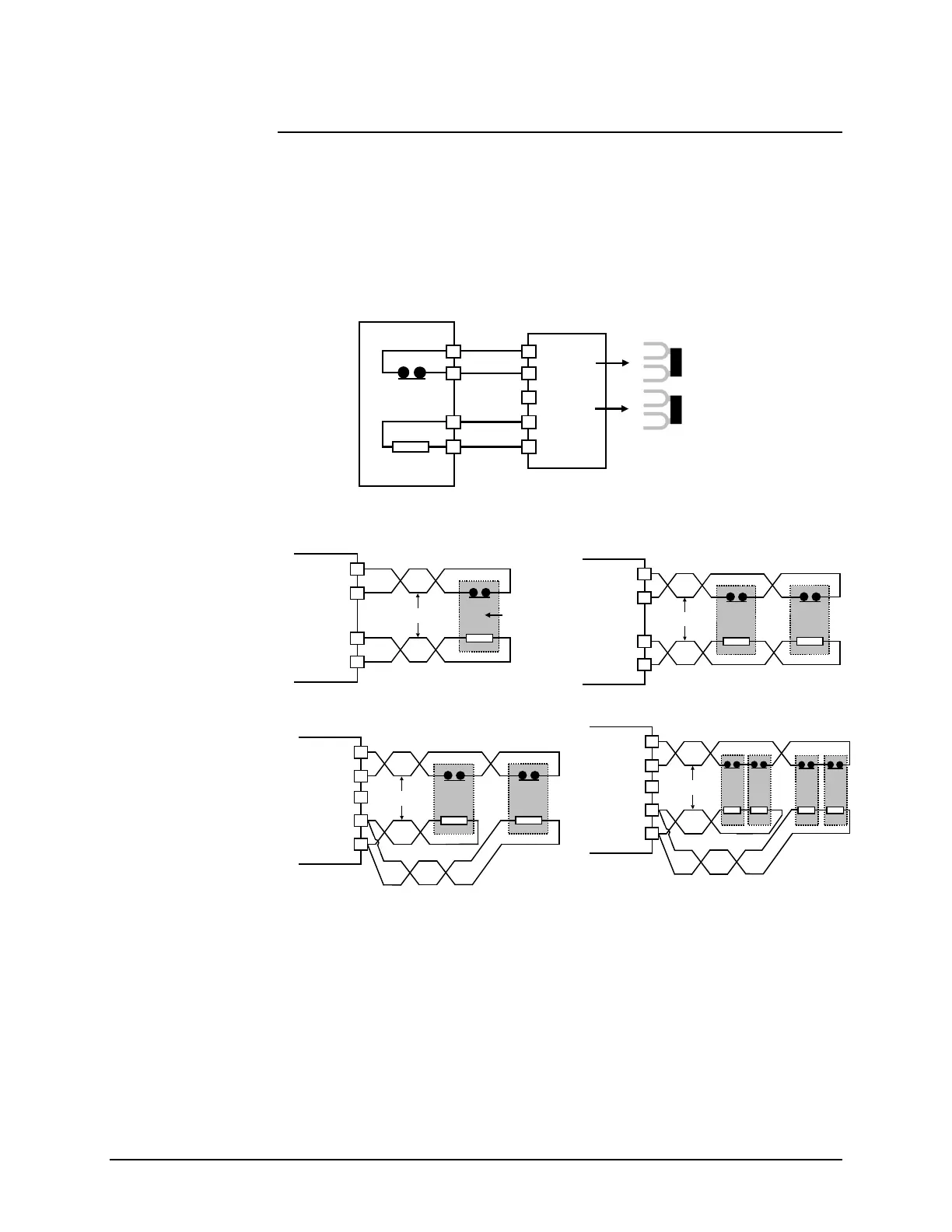
Disconnect the internal resistor from H1, H2, “X”, and “COM” terminals and then
connect according to diagram below. See figure below.
The PY2 (15A & 30A drives) has no shorting bars. For the PY2 (50A), disconnect the
jumper bars from “P” and “X”, then connect the leads of the regen resistor to “COM” and
“Y”. There is no connection for the thermostat.
1. Using the Table 16: Regeneration Resistor Selection above, determine the proper
circuit configuration, type D or S.
2. Make the connection wires as short as possible. Twist resistor leads together. Twist
thermostat connection together.
3. If possible, mount the resistor(s) above the amplifier. The resistors get hot so protect
adjacent equipment from the heat generated by the regen resistors.
How to connect a
Regen Resistor
CN5-3
CN5-2
CN1-10
CN1-11
External
Regeneration
Resistor
Twist the wires
for better EMC
Servo
Amplifier
One External Regen Resistor
Type D
Twist the wires
for better EMC
CN5-3
CN5-2
CN1-10
CN1-11
Servo
Amplifier
Two External Regen Resistors
(Series Connection)
Type S
Y
COM
X
H1
H2
Servo
mplifie
Regeneration
Resistor
}
}
Remove the
Jumper Bars
Twist the wires
for better EMC
Y
COM
X
H1
H2
Servo
Amplifier
Two External Regen Resistors
(Parallel Connection)
Type P
Twist the wires
for better EMC
Y
COM
X
H1
H2
Servo
Amplifier
Four External Regen Resistors
(Parallel/Series Connection)
Type SP
Artisan Technology Group - Quality Instrumentation ... Guaranteed | (888) 88-SOURCE | www.artisantg.com
 Loading...