PY Manual Copyright © 2006 SANYO DENKI AMERICA, Inc.
55
Pre-Operation
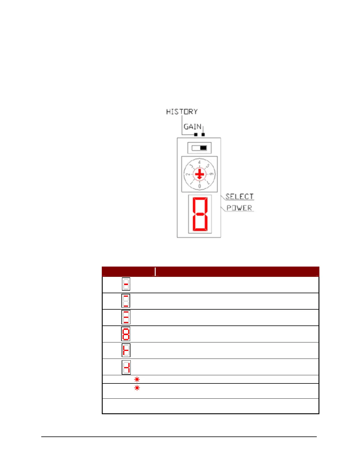
The amplifier has a 7-segment display, a power LED and a Charge LED on the face that
is used to indicate the operating status and alarm conditions. The display has two modes
(History and Gain) that are selected by switching a DIP switch above the LED. When
placed in History mode, the seven-position dial can be adjusted to see the current staus
(0) or one of the last seven alarms (1-7).
In Gain Mode the current status is also displayed.
Table 17: Amplifier Status Display
Display Status
Control power (r, t) is present and the amplifier-ready output
(RDY) signal is ON.
The bus power (R, S, and, T) is present but the start ready
complete (SRDY) signal is OFF.
The bus power (R, S, and, T) is present and the start ready
complete (SRDY) signal is ON.
The Servo ON signal is ON.
In the position/velocity control, the forward over-travel limit
(PROT) input is active.
In the position/velocity control, the reverse over-travel limit
(NROT) input is active.
Power The control power supply +5V is present.
Charge
The bus capacitors are charged. While this LED is ON be careful
of high voltage.
Flashing Code
When an alarm occurs then the alarm code is flashed on the
7-segment display.
Amplifier Status
Display
Rotating in
a figure 8
Artisan Technology Group - Quality Instrumentation ... Guaranteed | (888) 88-SOURCE | www.artisantg.com