EasyManua.ls Logo

Sanyo PLV-Z3000 Service Manual

Sanyo PLV-Z3000
134 pages
To Next Page IconTo Next Page
Page #1 background imageLoading...
Page #1 background image
FILE NO.
SERVICE MANUAL
REFERENCE NO. SM5111017-00
PRODUCT CODE :
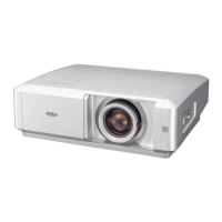
PLV-Z3000 ME4A 1 122 447 00 U.S.A., Canada
PLV-Z3000 PE4A 1 122 448 00 Europe, Asia, Africa
PLV-Z3000 PE4C 1 122 448 02 U.K.
Multimedia Projector
Chassis No. ME4-Z300000
NOTE: Match the Chassis No. on the rating
sheet on the cabinet with the Chassis
No. in the Service Manual.
If the Original Version Service
Manual Chassis No. does no t
match the unites, additional Service
Literature is required. You must refer
to ā€œNoticesā€ to the Original Service
Manual prior to servicing the unit.
MODEL NO. PLV-Z3000
U.S.A., Canada, Europe,
U.K. Asia, Africa
Original Version

Table of Contents

Other manuals for Sanyo PLV-Z3000

Questions and Answers:

Sanyo PLV-Z3000 Specifications

General IconGeneral
Matrix size0.7 \
Vertical scan range50 - 100 Hz
Horizontal scan range15 - 80 kHz
Projection technologyLCD
Contrast ratio (typical)-
Screen size compatibility40 - 300 \
Aspect ratio16:9
RS-232 ports1
Dimensions (WxDxH)400 x 146 x 346 mm
Lamp typeUHP
Lamp power165 W
Light source typeLamp
Service life of light source2000 h
Service life of light source (economic mode)3000 h
FocusManual
Focal length range22.3 - 45.3 mm
Noise level19 dB
Dot clock scanning frequency100 MHz
Serial interface typeRS-232
Component video (YPbPr/YCbCr) in3
Weight and Dimensions IconWeight and Dimensions
Weight7500 g

Summary

SERVICE MANUAL

Multimedia Projector

Official title of the device covered by the manual.

Safety Instructions

Safety Precautions

Essential safety guidelines and precautions for handling the projector.

Product Safety Notice

Important notice regarding component replacement and product safety.

Service Personnel Warning

Warnings for service personnel regarding potential hazards during maintenance.

Technical Specifications

Specifications

Detailed technical data and performance characteristics of the projector.

Circuit Protections

Fuse

Information about the fuse, its location, and replacement procedure.

Thermal Switch

Details on the thermal switch, its function, and reset procedure.

Circuit Protection

Warning Temperature and Power Failure Protection

How the projector protects itself from overheating and power issues.

Maintenance and Cleaning

Warning Indicator

Explanation of the warning indicator states and related troubleshooting steps.

Cleaning the Air Filters

Detailed steps for cleaning or replacing the projector's air filters.

Lamp Replacement

Lamp Replacement Procedure

Step-by-step instructions for safely replacing the projection lamp unit.

Lamp Handling Precautions

Critical safety warnings and precautions for handling high-pressure lamps.

Lamp Replacement Counter Reset

Steps to reset the lamp replacement counter after a new lamp is installed.

Service Port

Service Port Operation

How to enable and disable the service port for diagnostics and updates.

Mechanical Disassemblies

Cabinet Top Assembly Removal

Step-by-step instructions for removing the projector's top cabinet assembly.

Lamp Unit Removal

Steps for removing the projector's lamp unit.

Optical Unit Removal

Procedure for removing the projector's optical unit.

Power Unit Removal

Procedure for removing the power supply and ballast unit.

Optical Disassemblies

LCD Panel / Prism Assembly Removal

Procedure for removing the LCD panel and prism assembly.

LCD Panel/Prism Assembly Replacement Notice

Critical notice regarding LCD panel replacement and subsequent adjustments.

Optical Parts Location and Direction

Diagram and list showing the location and orientation of optical components.

Optical Adjustment

Electrical Adjustment

Service Adjustment Menu Operation

How to navigate and operate the projector's service adjustment menu.

Circuit Adjustment

Guidelines and cautions for adjusting projector circuits, emphasizing factory settings.

Service Adjustment Data Table

Table providing initial values and ranges for various service adjustments.

Chassis Block Diagram

Video Signal Processing and LCD Panel Driving Circuits

Detailed schematic showing video signal flow and LCD panel driving circuitry.

Fan Control Circuit

Schematic showing the fan control system, including speed regulation and temperature sensors.

Power Supply Circuit and Protection (1)

Schematic of the projector's power supply and protection circuits.

Power Supply Circuit and Protection (2)

Further details on power supply circuits and secondary power failure protection.

Motor Driving Circuit

Schematic showing motor driving circuits for lamp iris, door, and filter motors.

Troubleshooting

Indicators and Projector Condition

Table correlating projector indicators with specific operating conditions and fault states.

No Power Troubleshooting

Steps to diagnose and resolve issues related to the projector not powering on.

Troubleshooting Flashing Indicators

Diagnostic steps based on flashing indicator lights (orange, red, yellow).

Lamp Circuit Troubleshooting

Troubleshooting lamp driving signals, cover switch, and thermal switch.

No Picture Troubleshooting

Steps to diagnose and resolve issues when no picture is displayed across all input sources.

Control Port Functions

I/O Port Table of Main CPU

Pinout and function description for the main CPU (IC301).

Electrical Parts List

Mechanical Parts List

Mechanical and Optical Parts List

Diagrams & Drawings

Schematic Diagrams

Electrical schematics detailing the projector's internal circuitry.

Printed Wiring Board Drawings

Layouts of the printed wiring boards for component placement reference.

Parts Description and Schematic Reading

Pin Description of Electronic Components

Related product manuals