Chapter 2 Installation Electrical Installation
34 EM13x Series SMART MULTIFUNCTION METER
Voltage Input connection
The equipment installation shall conform to the following
instructions:
a) a switch or circuit-breaker shall be included in the building
installation as close as possible to the equipment supply
voltage;
b) It shall be in close proximity to the equipment and within
easy reach of the OPERATOR;
c) It shall be marked as the disconnecting device for the
equipment.
d) Before installing, ensure that all incoming power sources are
shut OFF. Failure to observe this practice can result in serious
or even fatal injury and damage to equipment.
e) The current sensors may not be installed in a panel where
they exceed 75% of the wiring space of any cross-sectional
area within the panel.
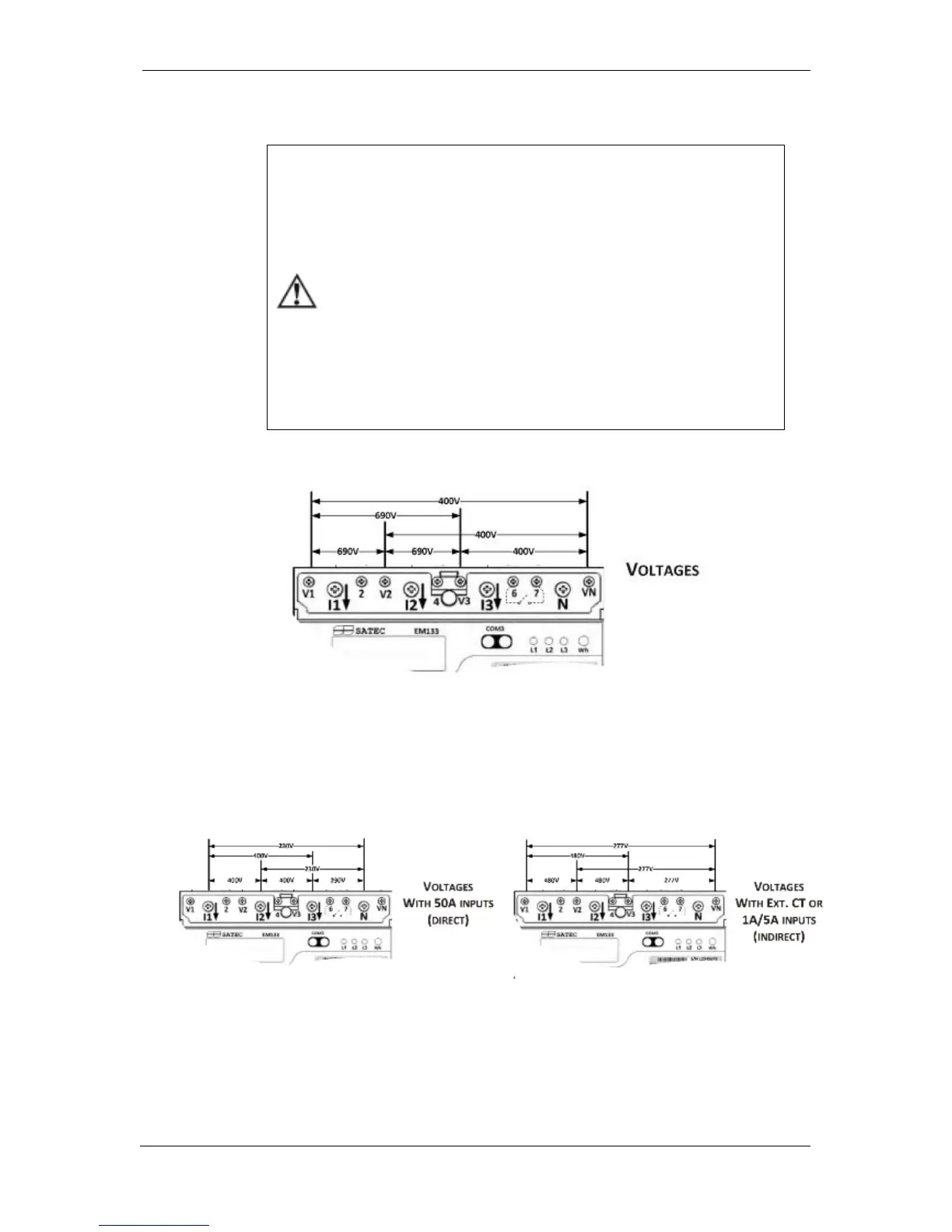
EM13x Series (with Aux. Power Supply) 690V Inputs (Standard)
Figure 2-9EM13X Series (with Aux. Power Supply) measured Voltage connections
690V inputs are usually used with direct connection. Use any of the
seven wiring configurations shown in Figures 2-8 through 2-15.
EM13X-SE model Voltage connections
Figure 2-10 EM13X-SE model measured Voltage connections
EM133-SE model with measuring nominal current 1A or 5A or 2.5mA
(using RS5), indirect connection – nominal voltage input is 120(207) to
277 (480) VAC.

 Loading...