EasyManuals Logo

Satec EM133 User Manual

Satec EM133
169 pages
To Next Page IconTo Next Page
To Previous Page IconTo Previous Page
Page #45 background imageLoading...
Page #45 background image
Chapter 2 Installation I/O Connections
EM13x Series SMART MULTIFUNCTION METER 45
4DI/2RO Module
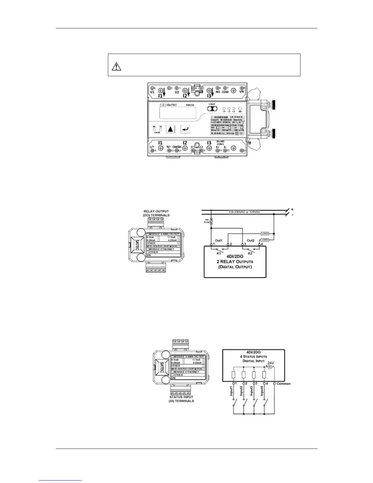
Before I/O Module installation ensure that all incoming power
sources are shut OFF. Failure to observe this practice can
result in serious or even fatal injury and damage to equipment.
Figure 2-10 4DI/2RO Module Assembly
Relay Outputs
There are two relay outputs provided for energy pulsing, alarms, or
remote control.
Figure 2-11 Relay Output Connection
Digital Inputs
Four optically isolated status inputs are provided for status monitoring,
pulse counting, external power demand period, and time
synchronization.
Figure 2-12 4 DI/2DO - Digital Input Connection

Table of Contents

Other manuals for Satec EM133

Questions and Answers:

Question and Answer IconNeed help?

Do you have a question about the Satec EM133 and is the answer not in the manual?

Satec EM133 Specifications

General IconGeneral
BrandSatec
ModelEM133
CategoryMeasuring Instruments
LanguageEnglish

Related product manuals