26 GB
• Before you actuate the On/Off switch, make sure
that the saw blade is correctly tted and that the
machine’s moving parts run smoothly.
• Before you connect the machine to the power
supply, make sure the data on the rating plate is
the same as that for your mains.
9. Attachment
ATTENTION!
Before all maintenance, set-up and assembly work
on the band saw, unplug the mains plug.
Assembly tools
1 Open-ended spanner, size 10/13
1 Allen key, size 3
1 Allen key, size 6
The saw table is not assembled for packaging rea-
sons.
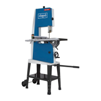
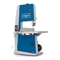
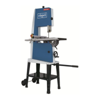
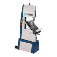
9.1. Assembling the saw table (Fig. 1-4)
• Open the side covers (11) by undoing the top (13)
and bottom (10) cover locks. First unlock the top
cover lock (13) with the help of the 6 mm Allen key
(28) by turning this counter-clockwise. Then un-
lock the bottom cover lock (10) by unscrewing it
counter-clockwise.
• Set the swivel section to 30° by loosening the saw
table locking handle (21) (g. 2).
• Guide the saw table (7) over the saw blade (22).
• Screw the saw table (7) to the swivel section (18)
with 4 M6x12 hex screws. Do not fully tighten the
screws.
• Swivel the saw table into the 0° position and tight-
en the saw table locking handle (21).
• Align the tabletop parallel to the saw blade. Tight-
en the 4 hex screws.
• Once adjustment is complete, close the side cover
(11) again with the bottom (10) and top (13) cover
locks in reverse order.
• Fit the M6x30 (34) screw with the 6mm (33) wash-
er, the 6mm (32) spring washer and the wing-nut
to the saw table (g. 3).
• Loosen the 3 hex nuts (X) ca. 2 turns and slide the
swivel section with the mounted
• saw table. The saw band must run centrally in the
table insert (6) (g. 3). Then tighten the 3 hex. nuts
(X) again (g. 4).
9.2. Tensioning the saw band (Fig. 1a)
ATTENTION! If the saw is at a standstill for an ex-
tended period the saw band tension must be re-
lieved, i.e. before switching the saw on it is neces-
sary to check the saw blade tension.
• Turn the clamping screw (1) clockwise to tension
the Bandsaw blade (22). The correct tension of
the saw band can be determined by pressing the
nger laterally against the saw band, roughly cen-
trally between the two saw band rollers (2+8). The
Bandsaw blade (22) should only depress slightly
(approx. 1-2 mm) here.
• The sufciently tensioned saw band makes a me-
tallic sound when tapped.
• Relieve the saw band tension if it is not in use
for an extended time, so that it does not become
overstretched.
ATTENTION! With high tension, the saw band may
break. RISK OF INJURY! If the tension is too low,
the driven saw band roller (8) may spin, resulting in
the saw band coming to a standstill.
9.3 Adjusting the saw band (Fig. 1a+1b)
ATTENTION! Before it is possible to implement the
saw band setting, the saw band must be tensioned
correctly.
• Open the side covers (11) by undoing the top (13)
and bottom (10) cover locks. First unlock the top
cover lock (13) with the help of the 6 mm Allen key
(28) by turning this counter-clockwise. Then un-
lock the bottom cover lock (10) by unscrewing it
counter-clockwise.
• Slowly turn the saw band roller (2) clockwise. The
Bandsaw blade (22) should run centrally on the
saw band roller (2). If this is not the case, the angle
of the top saw band roller (2) must be corrected.
• If the Bandsaw blade (22) runs more towards the
rear edge of the saw band roller (2) then the set
screw (15) must be rotated anticlockwise.
• Open the locking screw for the top saw band roller
(14).
• Turn the bottom saw band roller (8) slowly by hand,
to check the position of the Bandsaw blade (22).
• If the Bandsaw blade (22) runs more towards the
front edge of the saw band roller (2) then the set
screw (15) must be rotated clockwise.
• After setting the top saw band roller (2), check the
position of the Bandsaw blade (22) on the bot-
tom saw band roller (8). The Bandsaw blade (22)
should also lie centrally on the saw band roller (8)
here. If this is not the case, the angle of the top
saw band roller (2) must be adjusted again.
• Turn the saw band roller a few times, until the ad-
justment of the top saw band roller (2) acts on the
saw band position on the bottom saw band roller
(8).
• Tighten the locking screw for the top saw band
roller (14).
• Once adjustment is complete, close the side cover
(11) again with the bottom (10) and top (13) cover
locks in reverse order.
9.4. Adjusting the saw band guide (Fig. 5 - 8)
Both the support bearing (36 + 42) and the guide
pins (37 + 46) must be readjusted after every saw
band change.
• Open the side covers (11) by undoing the cov-
er locking mechanisms (10) with the help of the
screwdriver (29).
9.4.1. Top support bearing (36) ( Fig. 5)
• Undo Allen screw for top support bearing (35).
• Move support bearing (36) sufciently far that it
just no longer touches the Bandsaw blade (22)
(distance max. 0.5 mm).
• Retighten the Allen screw for the top support bear-
ing (35).
9.4.2. Adjusting the bottom support bearing
(42) (Fig. 7)
• Disassemble the saw table as per 9.1 in the op-
posite direction.
• Undo Allen screw for bottom support bearing (41).
 Loading...
