Installation and operating instructions
13 Vers. 1.0 2024_03
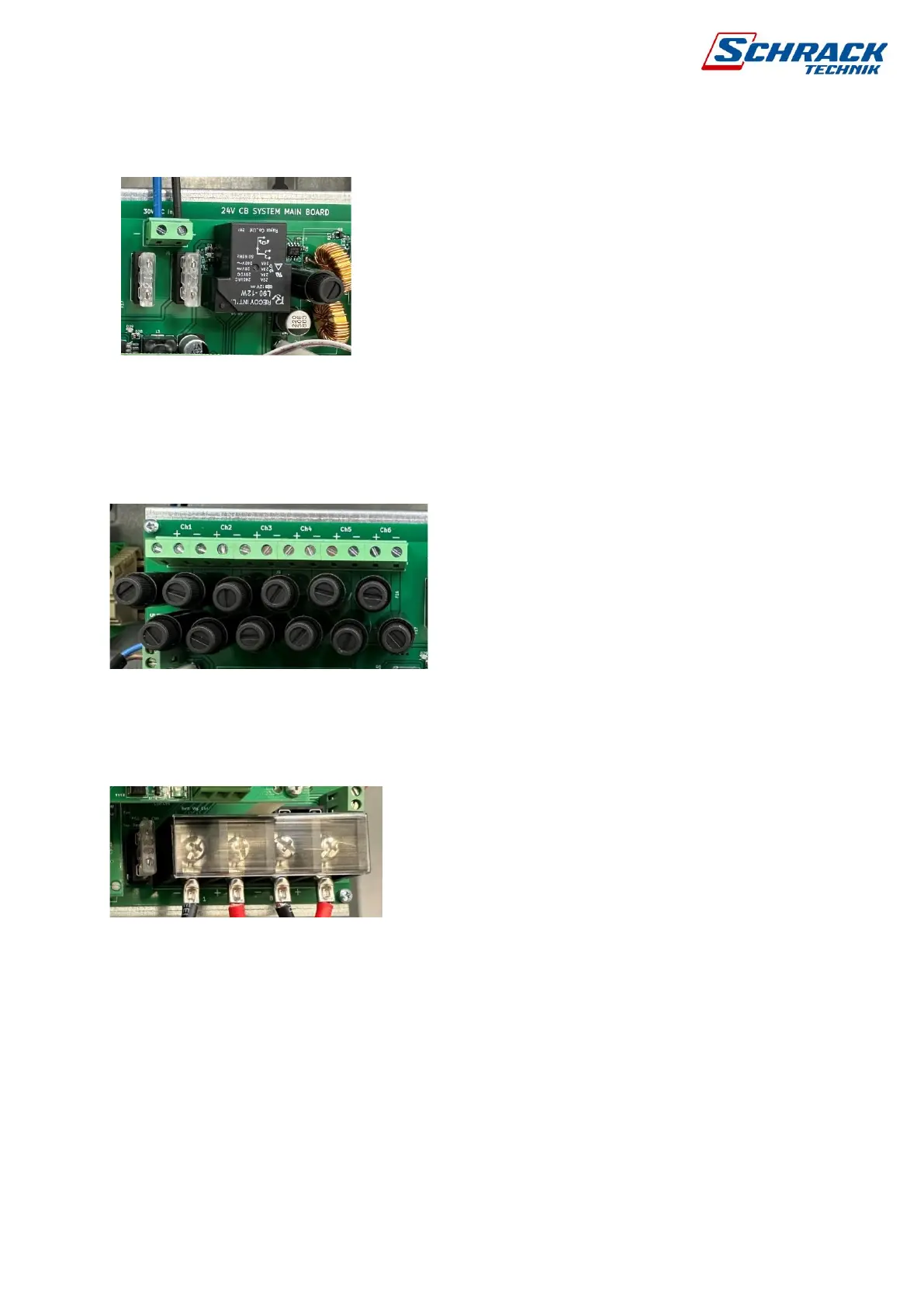
2.5 DC power supply and fuses
The system monitors the presence of the DC supply. There
are 25A fuses on both the positive and negative sides. If the
main supply is interrupted, the control panel will display an
AC error and will not receive information about the DC
voltage. If only a DC fault is displayed, the power supply
under the main board should be checked. The DC voltage
should be 31V at the terminals.
The 5A fuse for the charging circuit is located next to the
battery operation changeover relay. If the failure of the fuse
can be measured with an instrument, contact the service centre immediately as the charging
circuit must be checked.
2.6 Connection of circuits
Connect circuits polarity correctly starting from
CH1 + - terminal blocks. Maximum wire cross
section 2.5mm². Both positive and negative
branches of each circuit are secured by a 3.15A
glass fuse, size 5x20 (NLSI20315T).
2.7 Connection of batteries
Before connecting the batteries, remove one fuse above and next to the terminal block.
Connect the negative terminal of battery 1 to point BATT1 – using the supplied cable and the
positive pole to point BATT1+. With the second battery, do the same for BATT2 and BATT2+.
Connect the battery fuse (25A) only in AC mode. Always pay attention to the correct
polarity connection of batteries!