Installation and operating instructions
34 Vers. 1.0 2024_03
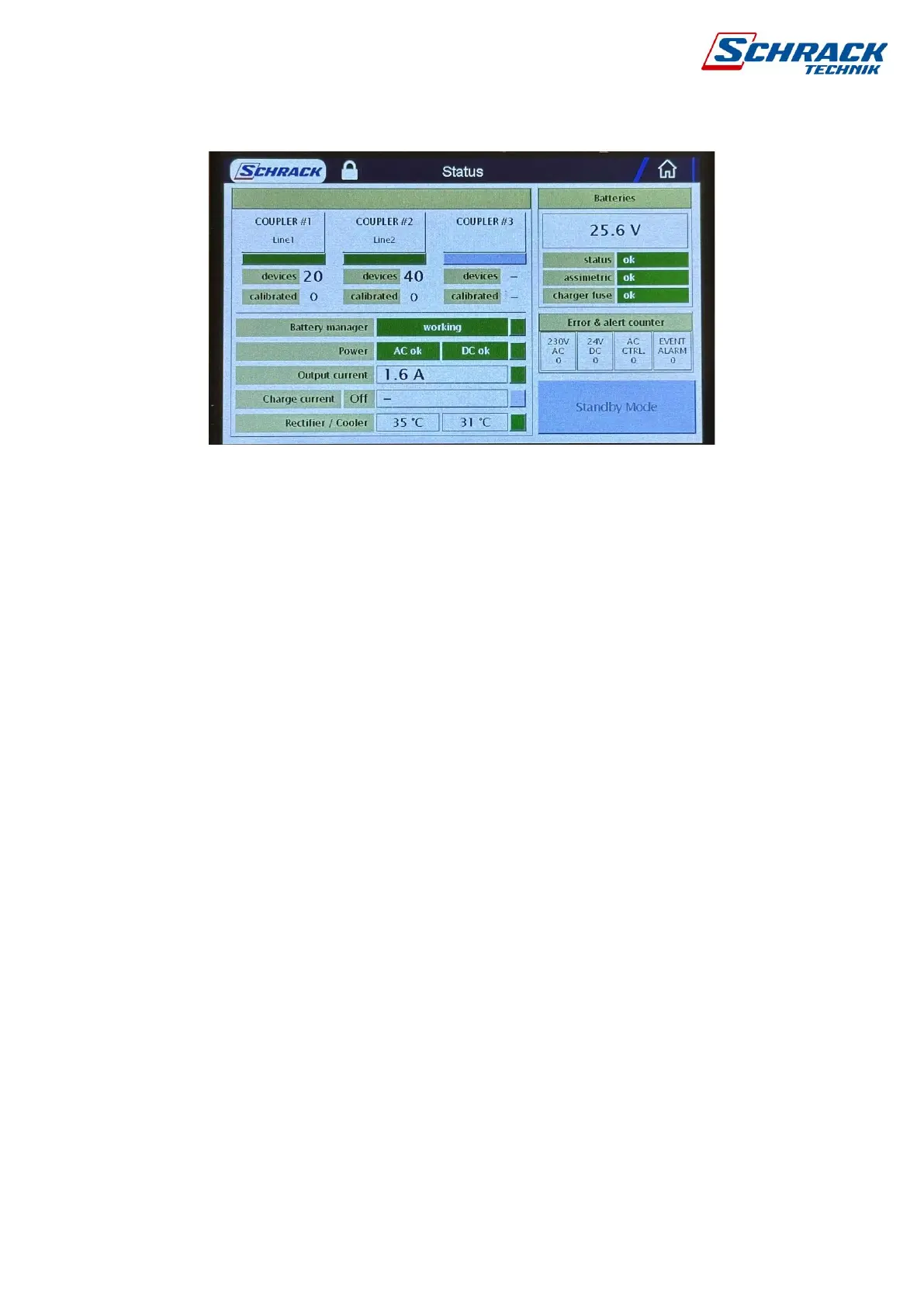
5.1.2 State
Here you will find all the important information about the system. After entering, we can activate
standby mode. To log in, click on the button and enter the software code, by default 5000.
Circuit information: normal state of 3-line interface modules is green, red when disabled,
gray when deactivated. You can see the names, the number of scanned and calibrated
luminaires.
Battery Manager Information: Status OK or Error. In case of supply voltage, AC and DC
voltages are checked separately. If there is only a DC voltage error, the power supply or fuse
must be checked. During charging, the magnitude of the charging current is shown in amperes.
There are two temperature sensors in the control cabinet, above 70°C it gives an error and
stops charging.
Battery information: In addition to the combined voltage of the two batteries, you can see
the fuse status of the battery (25A fuse), the asymmetry due to voltage difference between the
two batteries, and the state of the charge fuse.
Alarm counter: AC and DC errors, AC control activity and alarm event counter since startup.
Standby mode: Becomes available after logging in, puts the control panel into standby mode.
See 1.3.16