Assembly
09.00 | PGN-plus | Assembly and Operating Manual | en | 389296
27
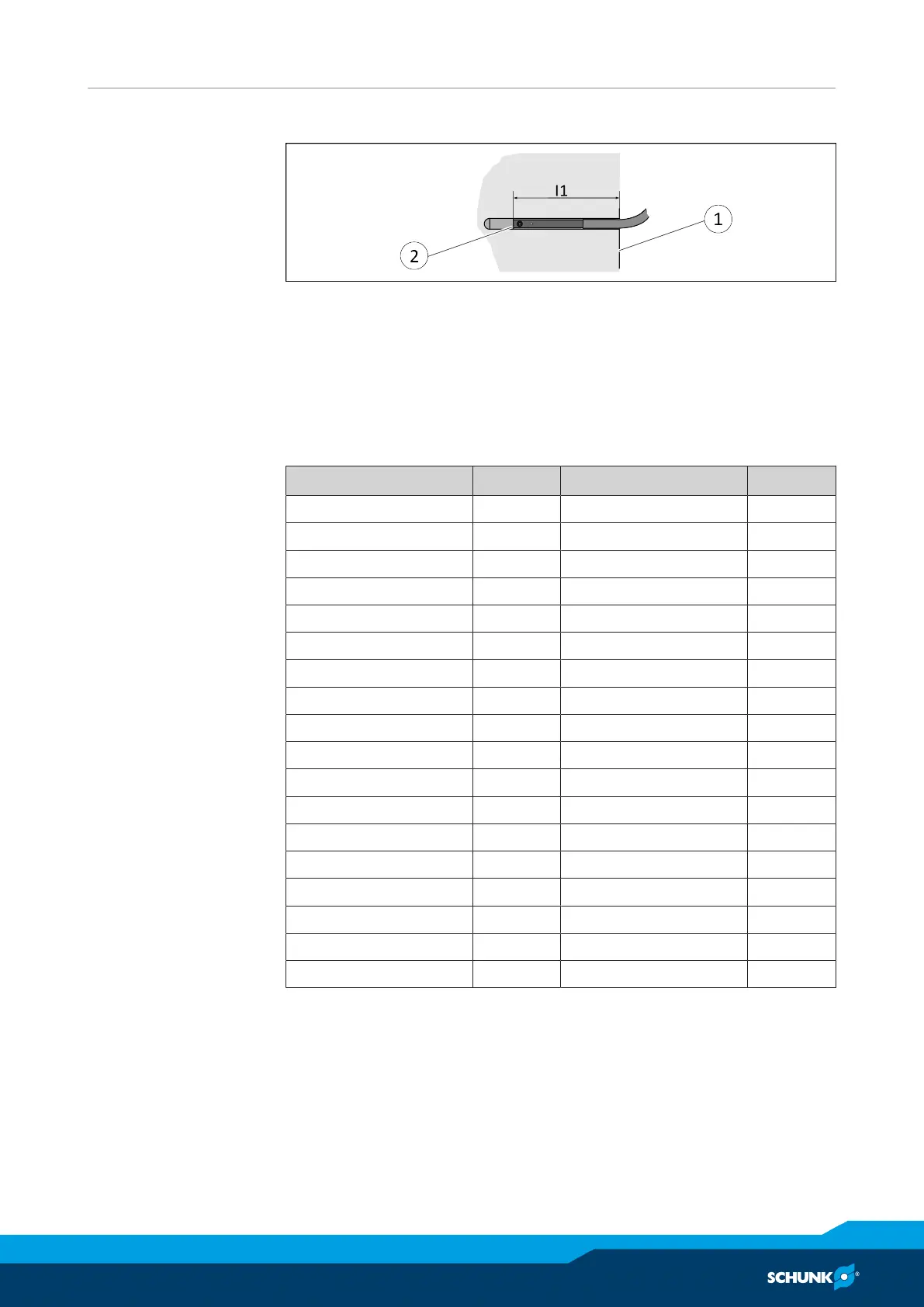
5.3.4 Setting dimensions for magnetic switches
* Setting dimension I1, from product bottom edge (1) to front sensor (2)
The setting dimension applies for the following sensors:
• Programmable magnetic switch MMS 22-PI1, not for sizes 50,
200, 240, 300 and 380
• Programmable magnetic switch MMS 22-PI2, not for sizes 50,
200, 240, 300 and 380
• Programmable magnetic switch MMS-P 22
Size l1* [mm] Size l1* [mm]
40 14.9 80-KVZ 48.5
40 AS 18.9 80 AS-KVZ / IS-KVZ 66.5
40 IS 23.9 100 27.7
40-KVZ 27.6 100 AS 19.9
40 AS-KVZ / IS-KVZ 36.6 100 IS 53.7
50 15.4 100-KVZ 54.2
50 AS 20.8 100 AS-KVZ / IS-KVZ 80.2
50 IS 31.4 125 23.0
50-KVZ 30.7 125 AS 59.6
50 AS-KVZ / IS-KVZ 46.7 125 IS 52.9
64 22.4 125-KVZ 55.5
64 AS 19.2 125 AS-KVZ / IS-KVZ 85.4
64 IS 40.4 160 31.4
64-KVZ 41.4 160 AS 71.9
64 AS-KVZ / IS-KVZ 59.4 160 IS 71.4
80 26.0 160-KVZ 68.9
80 AS 22.4 160 AS-KVZ / IS-KVZ 108.9
80 IS 44.0
* Dimension l1 Bottom edge of the product to front edge of the
sensor