EasyManuals Logo

SDLG WP6 User Manual

SDLG WP6
121 pages
To Next Page IconTo Next Page
To Previous Page IconTo Previous Page
Page #95 background imageLoading...
Page #95 background image
Service Manual for WP6 Diesel Engine
85
Fan heater Fan heater
Expansion
water tank
Relief valve cover
Engine oil radiator
Fan
Therm
ostat
Water
pump
Water outlet pipe
Cylinder cover
Engine block
Radiator
Air compressor
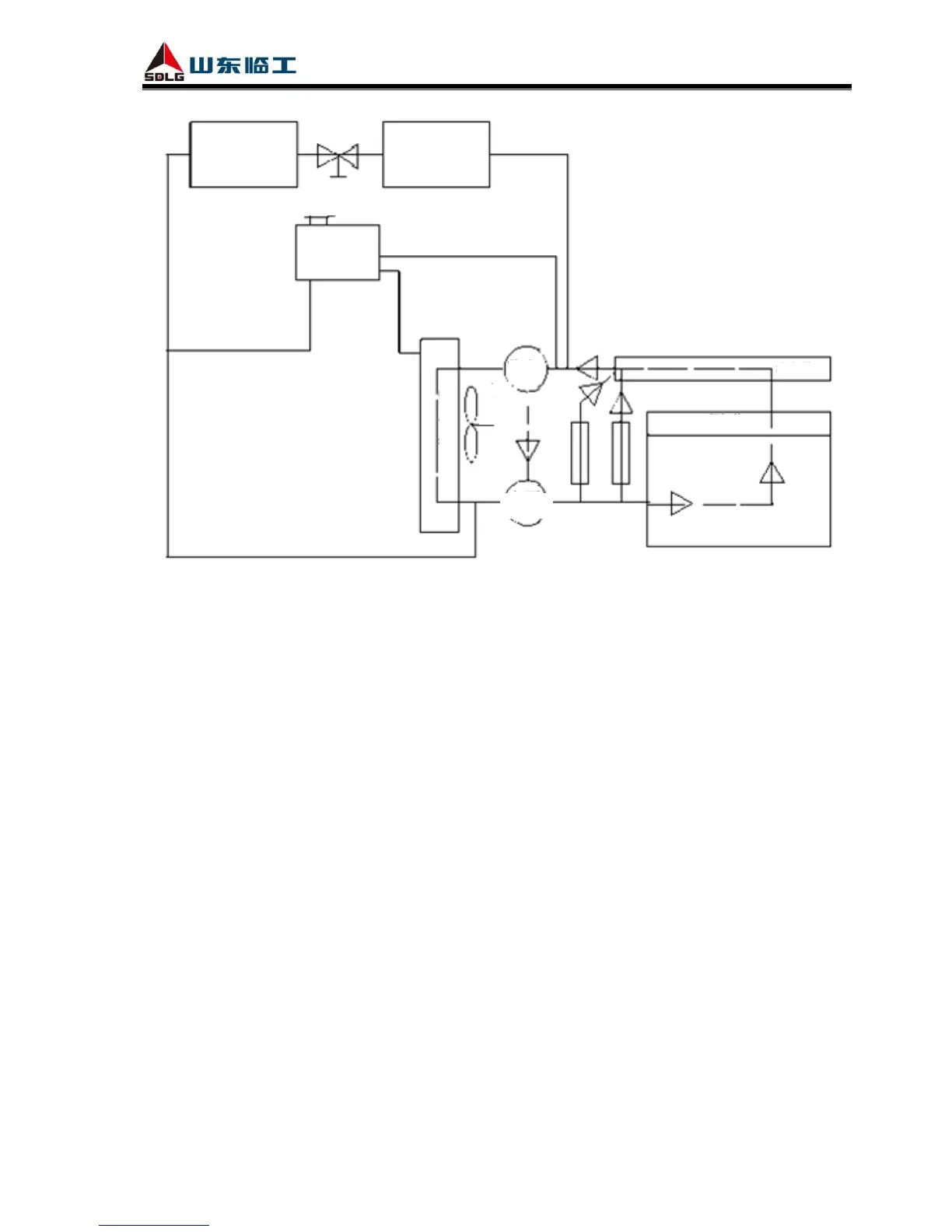
Fig. 3-48 Cooling route map of WP6 mechanical pump diesel engine
3812 Steps to Disassemble Cooling System
As shown in Fig. 3-47:
(1) Remove fan and connecting plate, refer to disassembly of fan for details.
(2) Remove the tensioning wheel.
(3) Remove the belt.
(4) Remove generator, generator support, crankshaft pulley and damper.
(5) Remove thermostat, refer to disassembly of thermostat for details. Remove water inlet pipe.
(6) Remove air compressor and hydraulic pump.
(7) Remove pipe joints of water pump and take down the pump, refer to disassembly of water
pump for details.
(8) Remove the middle cushion block.
3813 Steps to Assemble Cooling System
Assembling steps are contrary to disassembling ones.

Table of Contents

Questions and Answers:

Question and Answer IconNeed help?

Do you have a question about the SDLG WP6 and is the answer not in the manual?

SDLG WP6 Specifications

General IconGeneral
BrandSDLG
ModelWP6
CategoryEngine
LanguageEnglish