Installation and maintenance
R250
A.V.R.
8
LEROY-SOMER
4067 en - 2009.05 / b
3 - INSTALLATION -
COMMISSIONING
3.1 - Electrical checks on the AVR
- Check that all connections have been
made properly as shown in the attached
wiring diagram.
- Check that the position of the jumper
corresponds to the operating frequency.
- Check whether the ST4 jumper or the
remote adjustment potentiometer have
been connected.
3.2 - Settings
The different settings made during the
trial are to be done by qualied personnel.
Respecting the load speed specied on
the nameplate is vital in order to start a
settings procedure. After operational
testing, replace all access panels or
covers.
The only possible settings on the
machine are to be done with the A.V.R.
3.2.1 - R250 settings (SHUNT system)
Initial potentiometer positions
- voltage setting potentiometer P1 for the
A.V.R.: full left
- remote voltage setting potentiometer: in
the middle.
Operate the alternator at its rated speed: if
the voltage does not rise it is necessary to
re-magnatise the magnetic circuit.
- slowly adjust the voltage potentiometer of
the A.V.R. P1 until the output voltage reaches
its rated value.
- Stability setting with P2.
3.2.2 - Special type of use
Excitation circuit E+, E- must not be left
open when the machine is running:
A.V.R. damage will occur.
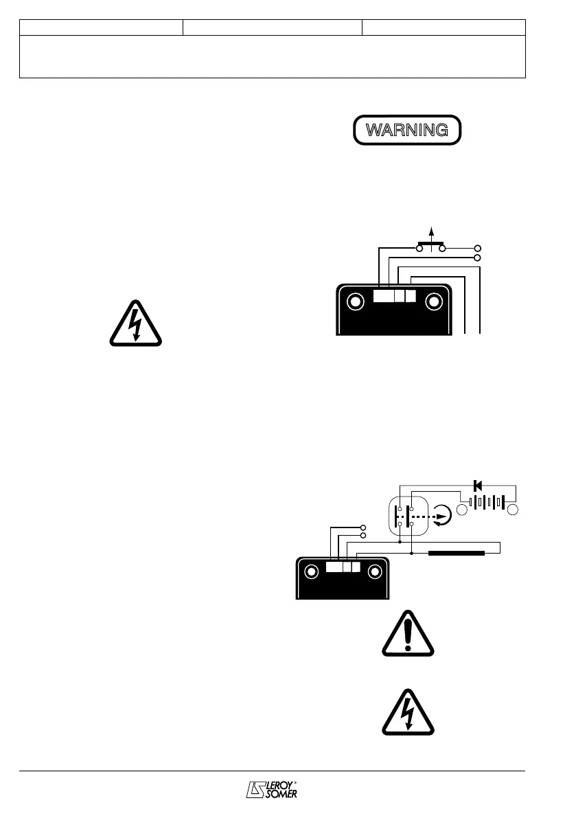
3.2.2.1 - R250 eld weakening (SHUNT)
The exciter is switched off by disconnecting
the A.V.R. power supply (1 wire - 0 or 110V).
Contact rating: 16A - 250V AC
Do not reclose the power supply until the
voltage has reached a value ≤15% of the
rated voltage (approximately 5 seconds
after opening)
3.2.2.2 - R250 eld forcing
The battery must be isolated from the
mass.
Exciter eld may be at line potential.
WARNING
Battery (B Volt)
+
-
t
(400V - 10A)
Excitation Inducer
Diode
E+
E-
0V
110