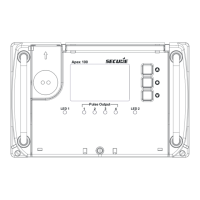
BGX501-742-R01, APEX 100 User Manual
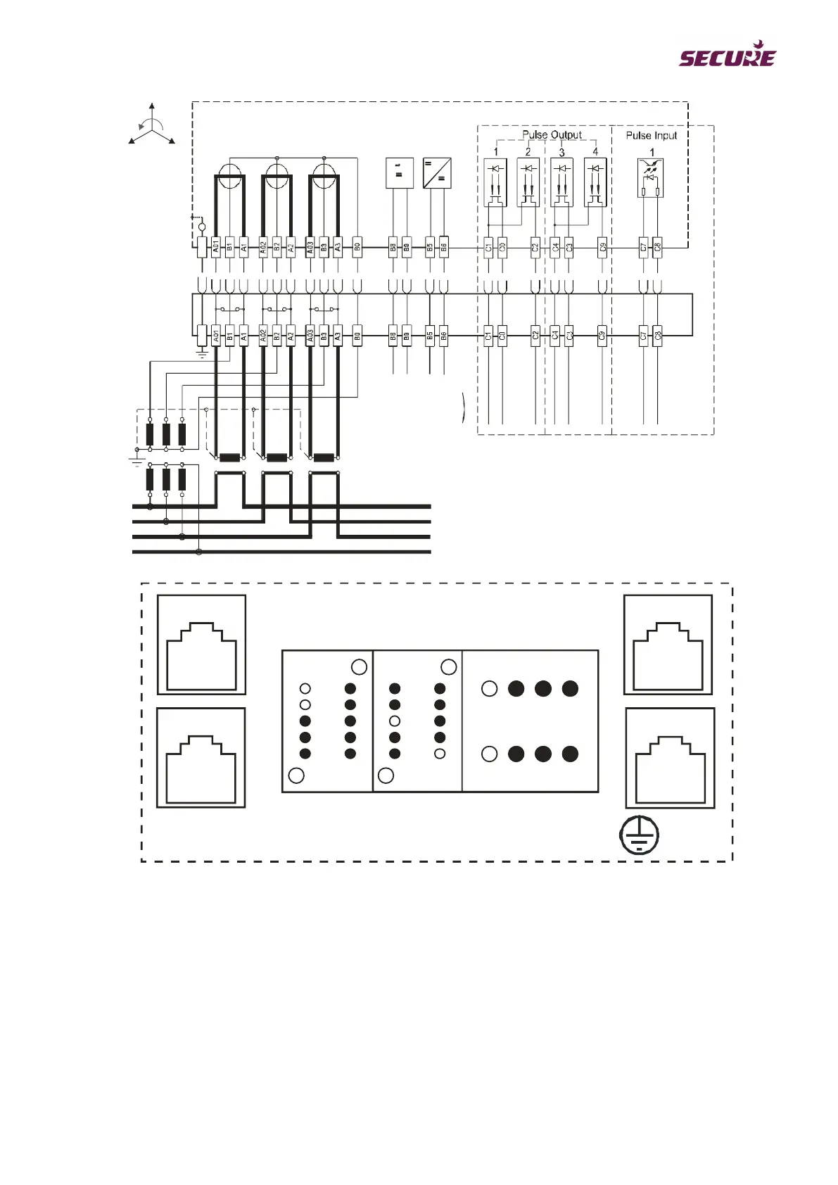
R/L1
Y/L2
B/L3
N
˜
Aux.1
Aux.2
(
(
48-276V
AC/DC
(
48-276V
AC/DC
3 Phase, 4 Wire
R
YB
RS232
Ethernet
RS485 IN
RS485 OUT
C
B A
04 03
02 01
4 23 1
6
8
9
7
5
1
3
4
2
0
6
8
9
7
5
1
3
4
2
0
Figure 12: 3-Phase 4-Wire Wiring Diagram Example
2.2.1 Rear Sealing Arrangement
When the meter is fitted into the rack, a cover can be fitted which conceals all the rear connectors. The figures
below show the sealing points for the rear cover. The figures show single and double rack examples with an
enlarged detailed view of a sealing point (A).