BGX501-742-R01, APEX 100 User Manual
A total of 12 Pulse I/Os are possible depending on your variant, factory setup and country destination (see
Table 1: Pulse I/O VariantsTable 1: Pulse I/O Variants). The default is 1 pulse input (2 fixed status types and 2
counter types) and 4 pulse outputs.
The remaining four are factory options which will be fitted as per the variant or model.
Pulse input rating 24 to 40V DC max @ 100 mA
Pulse output rating 110V-230 V AC/DC @ 100 mA (Pulse outputs have a volt free contact).
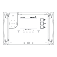
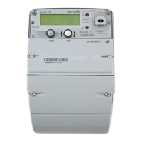
Pulse Outputs
Apex 100
1
LED 1 LED 2
2
3
4
Pulse Output
Figure 16: Front View showing Pulse Output LEDs
Pulse Output LEDs
A total of four LED indications are provided with two LED indications on fixed pulse outputs and the other two
LEDs will have a configurable option for any remaining pulse I/Os (see Figure 16).
Each Pulse output is linked with an LED output. The same information can be taken from pulse output as well
as the LED output.
Pulse Input
Pulse Input can be of the counter type or status type. The possible combinations for counter and status type
inputs are shown in table 1:
Any one of the status type pulse inputs can be used for a time synch pulse. Status and Counter information
shall is available in display and Modbus.
Note: The Input Counter and Status are both available on Modbus.