ENGLISH
www.sematic.com
Changes can be made without notice
Upgrade from Digidoor Controller
43
811-000-000 SDS© DC-PWM Compatible • Edition 25 March 2016
16 UPGRADE FROM DIGIDOOR CONTROLLER
• Eliminate the transformer 220/24 V with all its cables because the new SDS is fitted with an in-built switching
transformer
• Disconnect all the connectors to be substituted on the controller and connect them again to the new controller
using the connectors-adatpers Code nr. B066AAPX; this way no wiring operation is necessary and the
substitution is quick and easy. IMPORTANT: Please check the signal logic and the voltage range of the in-
coming signals from the control board. In case all the parameters do not correspond to the range and logics
given in chapter 4, it is possible to instal the Sematic interface kit code no. B066AAPX and follow the
instructions enclosed to it and in chapter 7.
• If the connectors-adapters Code nr. B066AAPX are not available: disconnect the wires from the old connectors
and connect them again following the correspondence given in the underneath table
• Connect the 220 Vac input to the SDS controller by means of the feeding cable supplied code no. E066AAWX-
A
• Select option EMULATION DIGIDOOR 1Nm or EMULATION DIGIDOOR 2Nm from the Menu General Option (see
§ 8.10 (pg. 32)) or programm parameter 22 using the keys on the frontal panel (03 o 04, see also § 5.3
(pg. 19)).
• Check the correct functioning
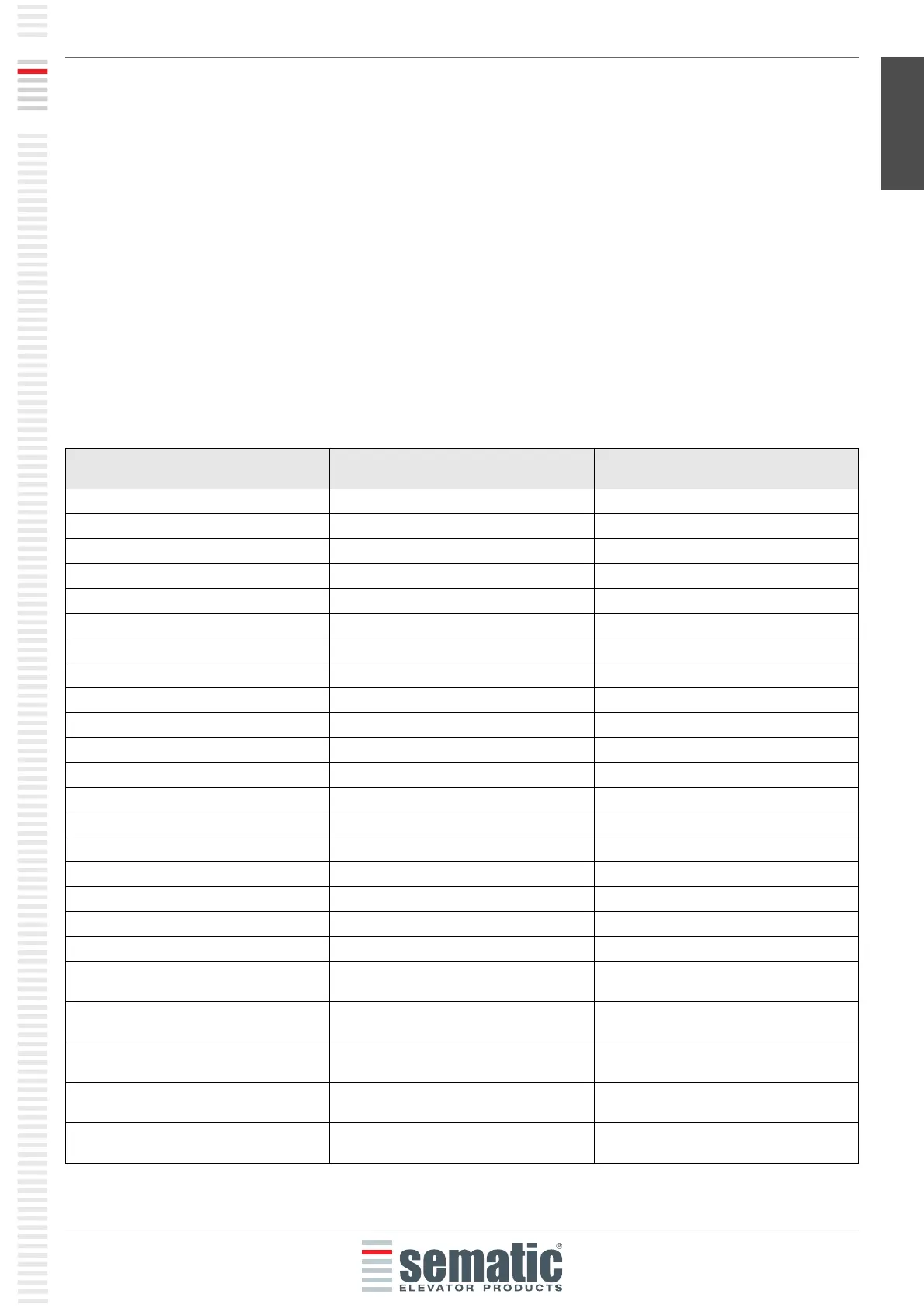
TERMINALS FUNCTION SEMATIC SDS Rel. 3
DC COMPATIBILE
1 IM reversing system N/C signal 1
2 IM reversing system N/O signal 2
3 Closing control Kc 3
4 IM reversing system COM signal 4
5 Ka opening control 5
6 COM 24 Vdc 15
7 24 Vac power NOT CONNECTED
8 24 Vac power NOT CONNECTED
9 Motor power 43
10 Motor power 44
11 Ra opening slow down Input signal 41
12 NOT CONNECTED
13 Rc closing slow down Input signal 42
14 NOT CONNECTED
15 COM 24 Vdc 15
20 Forced closing (nudging) Input control 22
21 15
22
23
24 Lc Closing limit switch input contact
(from the magnetic switch)
39
25 La Opening limit switch output contact
(to the main lift controller)
16
26 La Opening limit switch output contact
(to the main lift controller)
17
27 Lc Closing limit switch output contact (to
the main lift controller)
18
28 Lc Closing limit switch output contact (to
the main lift controller)
19