LR1110
User Manual Rev.1.0
UM.LR1110.W.APP March 2020
25 of 130
Semtech
www.semtech.com
3= FS
4 = RX
5 = TX
6 = Wi-Fi or GNSS geolocation
• Bootloader:
0: currently executes from boot-loader
1: currently executes from flash
The ResetStatus field is cleared on the first GetStatus() command after a reset. And that it is not cleared by any other
read/write command
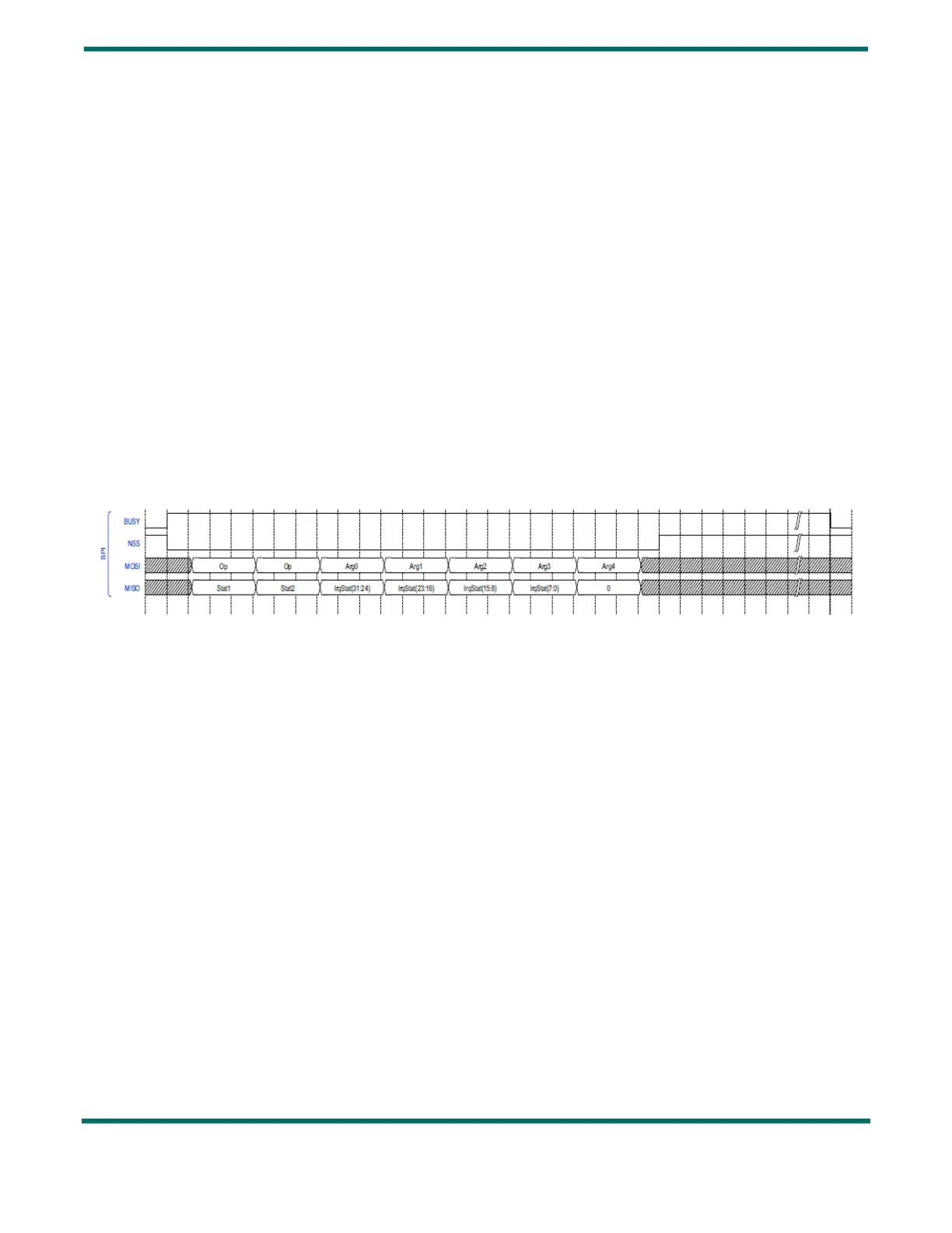
3.4 BUSY
DIO0 is used as Busy signalling: the BUSY pin is set high when the current command is being processed, and when the
device is not ready to accept a new command.
Therefore, the timing diagram of the BUSY signal is as follows:
Figure 3-3: BUSY Timing Diagram
The amount of time the BUSY line will stay high after the end of rising edge of NSS (T
SW
Mode) depends on the nature of the
command. The most common switching times T
SW
Mode are indicated in Section 2.6 "Modes Transitions & Timings" on page
22 .
3.5 Errors
3.5.1 GetErrors
The command GetErrors( ) returns the current pending errors that occurred since the last ClearErrors( ) command, or the
startup of the circuit.
It is possible to generate an interrupt on DIO9 or DIO11 when an error occurs. There is no masking of error possible.