20 | TeamConnect
Installing and connecting the TeamConnect components
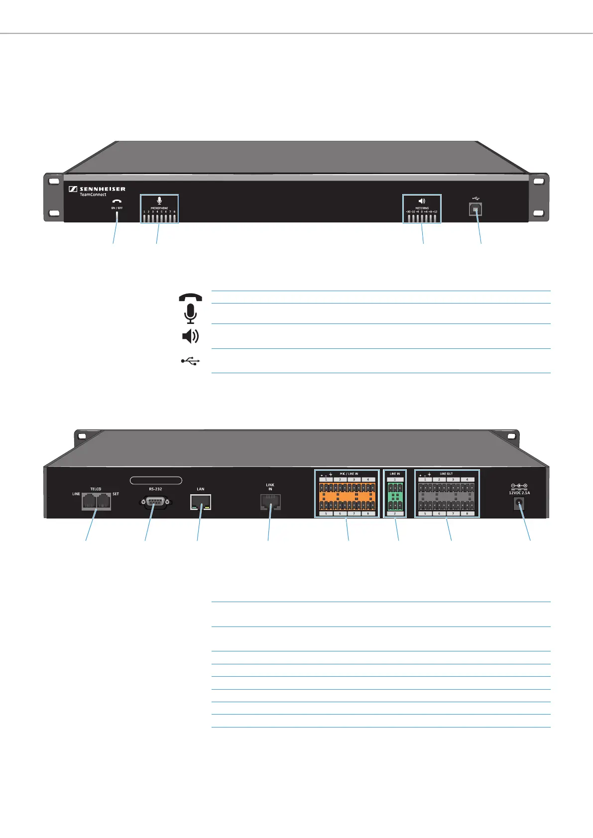
SL TeamConnect CU1 - Product overview
Front
Back
1 42 3
1 ON / OFF hook indicator Indicates if the telephone line is active (blue) or inactive (red)
2 MICROPHONE indicators
Indicate which microphone channels are active (blue) or muted (red)
3 METERING indicators
Indicate current meter level of the output chosen as the volume channel in the
Configuration Manager software
4 USB port
USB 2.0 port for connecting a computer - only for configuring the CU1 with the
Configuration Manager software
5 6 7 8 B9 0 A
5 TELCO telephone interface
LINE: RJ-11 socket for connecting the CU1 to the analog landline network
SET: RJ-11 socket for connecting an analog telephone set to the CU1
6 RS-232 control port
Control port for connecting a 3rd party media control system (e.g. AMX or
Crestron)
7 LAN RJ-45 socket Ethernet port (10/100 Mbps) for connecting the CU1 to a network
8 LINK IN RJ-45 socket Link input for connecting the CB1 to the CU1
9 MIC / LINE IN inputs Audio input terminal for microphone and/or line level inputs
0 LINE IN inputs Audio input terminal for line level inputs only
A LINE OUT outputs Audio output terminal
B Power adapter input 12 V DC 2.5 A