TeamConnect | 27
Installing and connecting the TeamConnect components
Using the GPIO port of the SL TeamConnect CB1
The SL TeamConnect CB1 has a GPIO port where you can connect external switches
or status indicators for controlling or indicating the mute status of a microphone
or for opening and closing the telephone line.
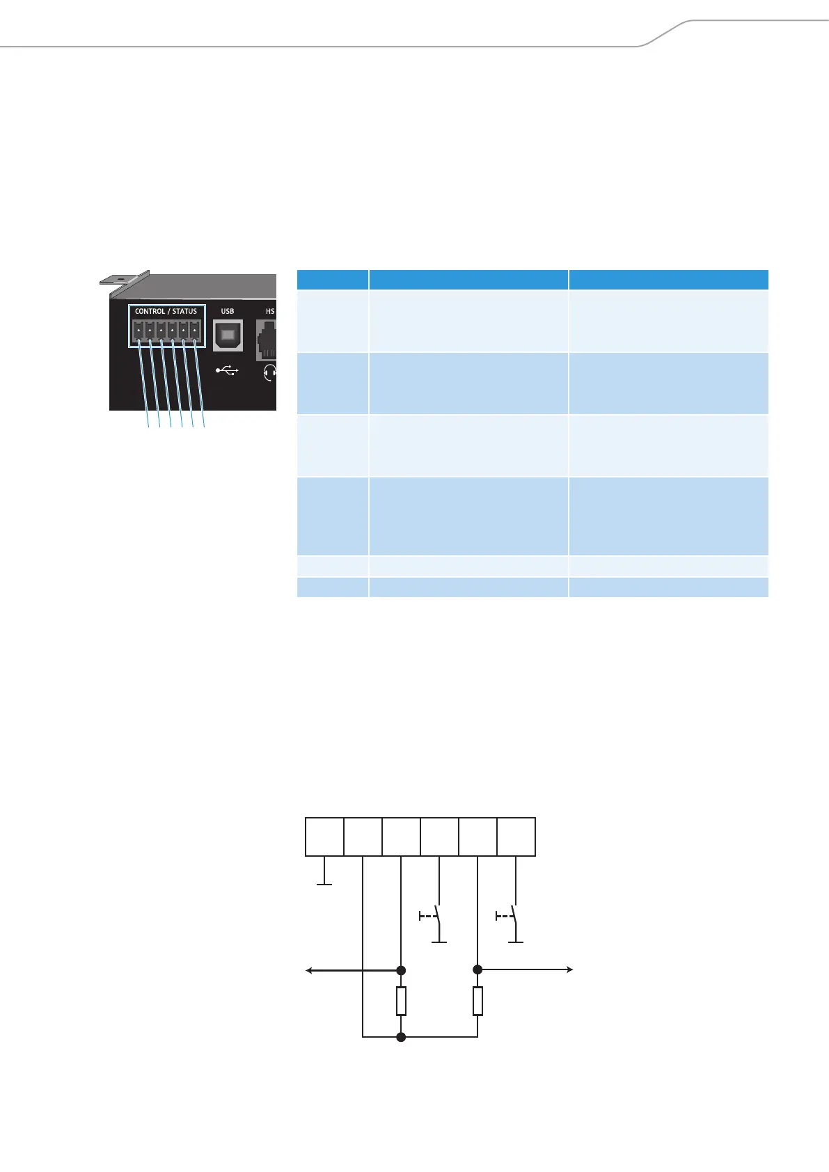
GPIO port pin allocation
For connecting switches or status indicators observe the following pin allocation:
Pin Allocation Function
Pin 1 Microphone mute control
(3.3 V; internal 10 kΩ pull-up)
Master mute function for all
microphones
• toggles at falling edge
Pin 2 Microphone mute status
(open collector)
Status of the master mute
function
• output level = low mute
Pin 3 On/Off hook control
(3.3 V; internal 10 kΩ pull-up)
Opens or closes the telephone
line
• toggles at falling edge
Pin 4 On/Off hook status
(open collector)
Sends the status of the
telephone line
• output level = low active
call
Pin 5 5 V DC (up to 40 mA) Power supply
Pin 6 Ground Ground
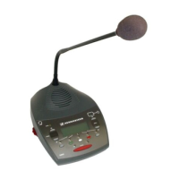
Using the GPIO port with Sennheiser equipment
Some of the Sennheiser SpeechLine microphones also have logic ports which can
be connected to the GPIO port of the SL TeamConnect CB1. This enables the control
of the master mute function and the indication of the mute status directly at the
microphones. For information on connecting the SpeechLine microphones refer
to the instruction manual of the SpeechLine microphone series.
Using the GPIO port with third-party equipment
When you are using third-party equipment please observe the following wiring:
6 5 4 3 2 1
Hook status
Mute status
5 V
10 kΩ
10 kΩ
Hook
Mute
6
5
4
3
2
1
Pin: