Operation Hardware Setup
After completing the calibration check:
1. Remove the meter from the test board.
2. Close the Phantom Load links by:
a. Loosening the lower screws on each link
b. Sliding the links up until they stop
3. Securely tighten all of the screws to prevent the slides from moving.
Testing
To interface with test equipment, the meter generates test pulses. The energy value assigned to
each test pulse is defined as the meter K
h
and can be configured to value that is a multiple of 0.2.
Meter Default K
h
Range (Wh/Pulse)
Form 9 1.8 Wh/pulse 0.2 to 40.8
Form 16 21.6 Wh/pulse 0.2 to 99.8
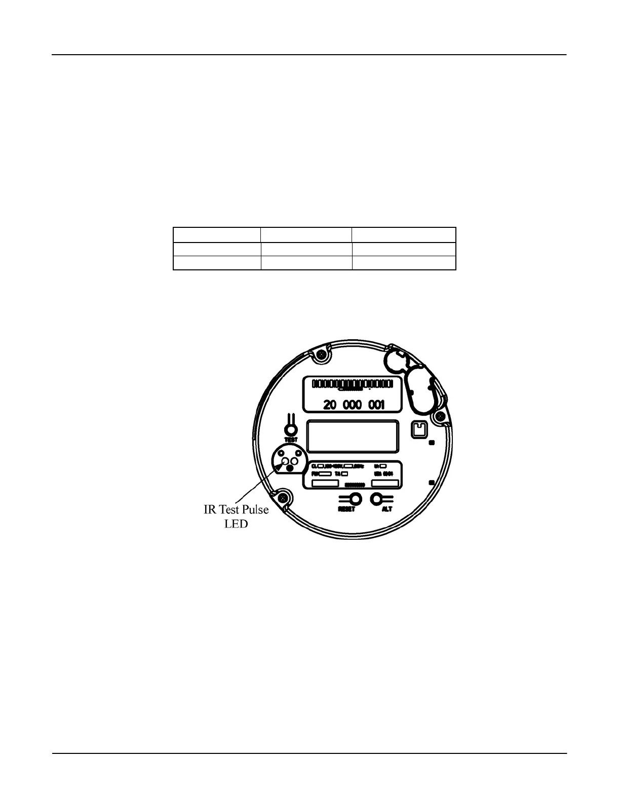
The test pulse output is compatible with all ANSI-rated laboratory and field test equipment and
is transmitted through the Infrared (IR) Test Pulse LED. When aligning the optical pick-up in
front of the IR Test Pulse LED. Position the pick-up so that it is perpendicular to the IR Test
Pulse LED. See Figure 3-2.
Figure 3-2: Location of the Infrared Test Pulse LED
Version 1.0 Operation 3-3