4
Installation notes
MOVI-C® CONTROLLER power UHX85A – P / power eco UHX84A–P
Manual – MOVI-C
®
CONTROLLER
21
4.2 MOVI-C
®
CONTROLLER power UHX85A – P / power eco UHX84A–P
MOVI-C®
CONTROLL
ER power
UHX85A –
P / power
eco
UHX84A–
P
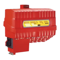
4.2.1 Connecting the controller to the PROFIBUS network
The following chapters describe the terminals and LEDs relevant for PROFIBUS
operation.
Front view (PROFIBUS) Designation Function
LAN3 LAN4
USB1
USB2 USB3
X1
On M
-24+
X24
L25.1
L25.4
L25.1
L25.4
X24
7613167499
LEDs
LED 25.1 Reserved
LED 25.2
Reserved
LED 25.3 PROFIBUS communication status
LED 25.4 System status
X24 connector: PROFIBUS (D-sub, 9-pin)
X24:9 GND (M5V) Reference potential for PROFIBUS
X24:8 RxD/TxD-N Receive/transmit negative signal
X24:7 N.C. Terminal not assigned
X24:6 VP
(P5V/100mA)
DC+5 V potential for bus terminator
X24:5 GND (M5V) Reference potential for PROFIBUS
X24:4 CNTR-P PROFIBUS control signal for re-
peater
X24:3 RxD/TxD-P Receive/transmit positive signal
X24:2 N.C. Terminal not assigned
X24:1 N.C. Terminal not assigned
22781455/EN – 05/2016

 Loading...