4
Installation notes
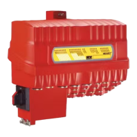
MOVI-C® CONTROLLER power UHX85A – R / power eco UHX84A–R
Manual – MOVI-C
®
CONTROLLER
24
4.3 MOVI-C
®
CONTROLLER power UHX85A – R / power eco UHX84A–R
MOVI-C®
CONTROLL
ER power
UHX85A –
R / power
eco
UHX84A–
R
4.3.1 Connecting the controller to the Ethernet network
You can connect the controller to the Ethernet network via the following Ethernet inter-
faces:
• X21 (RJ45 connector)
• X22 (RJ45 connector)
Front view (Ethernet) Designation Function
LAN3 LAN4
USB1
USB2 USB3
X1
On M
-24+
L23.1
L23.4
X21 X22
L23.1
L23.4
X21 X22
7995857803
X21: Ethernet interface with LEDs
LED
"Link" (green)
There is an Ethernet connection.
LED "Activ-
ity" (yellow)
Data is currently being exchanged via
Ethernet.
X22: Ethernet interface with LEDs
LED
"Link" (green)
There is an Ethernet connection.
LED "Activ-
ity" (yellow)
Data is currently being exchanged via
Ethernet.
LEDs
LED 23.1 Reserved
LED 23.2 Reserved
LED 23.3 Ethernet communication status
LED 23.4 System status
To connect the device to the Ethernet, connect one of the Ethernet interfaces to the
other network node using a category 5, class D twisted-pair cable in accordance with
IEC11801, edition 2.0.
INFORMATION
According to IEC 802.3, the maximum cable length for 10/100 MBaud Ethernet
(10BaseT/100BaseT) between 2 network nodes, is 100 m.
INFORMATION
In order to minimize the load on the end units resulting from unintended multi-cast
data transmission in Ethernet networks, SEW‑EURODRIVE recommends not to con-
nect any third-party end devices directly to units from SEW‑EURODRIVE.
• Connect third-party end devices via a network component that supports the IGMP
snooping functionality (e.g. managed switch).
→ Managed switches with IGMP snooping functionality are not required for Modbus/
TCP and PROFINET IO networks.
22781455/EN – 05/2016

 Loading...