EasyManua.ls Logo

Sewha SI 410 - User Manual

Sewha SI 410
75 pages
Print Icon
To Next Page IconTo Next Page
Loading...
Digital Weighing Indicator
SI 410
User Manual
Ver 2.0 2017.04.05
Question and Answer IconNeed help?

Do you have a question about the Sewha SI 410 and is the answer not in the manual?

Summary

BEFORE INSTALLATION

Caution; Warning Marks

Marks indicating potential death or serious injury.

INTRODUCTION

2-2. Cautions

Important safety precautions for using the indicator.

SPECIFICATION

3-1. Specification

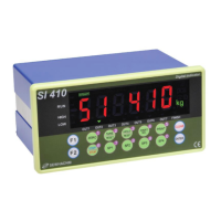
Detailed technical specifications of the SI 410 indicator.

Rear Panel Overview

3-4. Rear Panel

Diagram and explanation of the rear panel connections.

INSTALLATION GUIDE

Load Cell Installation Procedures

4-3. Load cell Installation

Instructions and precautions for connecting load cells.

SET-UP MODE

5-1. Set-up mode

Accessing and navigating the setup menu.

5-1-1. How to enter Set-up mode

Step-by-step guide to access the setup menu.

CALIBRATION MODES OVERVIEW

5-2. Test Weight Calibration Mode (Using test weight)

Adjusting weight balance using test weights.

5-2-1. Calibration

Process of adjusting weight balance using test weights.

TEST WEIGHT CALIBRATION

5-2-2. Start Test Weight Calibration Mode

Steps to initiate the test weight calibration process.

5-2-3. Setting “Capacity of weighing Scale”

How to set the maximum weighing capacity.

SPAN VALUE CALCULATION

5-2-6. Calculating span value

Steps to calculate the span value for calibration.

CALIBRATION COMPLETION

Span value calculation

Process of calculating the span value during calibration.

SIMULATION CALIBRATION MODE

5-3. Simulation Calibration Mode (Calibrate without Test weight)

Calibrating without test weights using load cell capacity.

5-3-1. Simulation Calibration Mode Start

Steps to start the simulation calibration process.

SIMULATION CALIBRATION CONFIGURATION

5-3-2. Setting Capacity of Load Cell

Setting the capacity of the connected load cell.

SIMULATION CALIBRATION STEPS

5-3-5. Inputting Max Output (Rated Output Voltage; mV)

Inputting the load cell's rated output voltage.

CALIBRATION ERROR TROUBLESHOOTING

Error handling during calibration

Information on calibration errors and troubleshooting.

F-FUNCTION SETTING GUIDE

5-4. F-FUNCTION Setting

Guide to setting various F-Functions in the indicator.

5-4-1. F-FUNCTION Setting

Step-by-step guide to setting F-Functions.

F-FUNCTION LIST

5-4-2. F-Function List

Comprehensive list of F-Functions and their definitions.

F-Function List (Continued)

Continuation of the F-Function list.

WEIGHING MODES

HIDDEN FUNCTION ACCESS

5-4-3. Hidden Function

Accessing and using hidden functions.

HIDDEN FUNCTION SETTINGS

SET POINT VALUE INPUT

5-5. Set Point value input (SP1~SP4)

How to input Set Point values.

TEST MODES OVERVIEW

5-6. Test Mode

Accessing and using the test modes.

DIAGNOSTIC TEST PROCEDURES

ANALOG OUTPUT DIAGNOSTIC TEST

INTERFACE OPTIONS

6-1-1. Main Serial Interface

Details on the main RS-232 serial interface.

SERIAL INTERFACE CONFIGURATION

DATA FORMATS

COMMAND MODE AND READ COMMANDS

6-1-5. Read Command

List of commands to read data from the indicator.

WRITE COMMANDS

6-1-6. Write Command

List of commands to write data to the indicator.

COMMAND DETAILS (F-FUNCTION 202;212-01)

6-1-7. Read COMMAND for SI410 (Under F-function 202;212-01)

Details of read commands for F-function 202/212-01.

6-1-8. Write COMMAND for SI410 (Under F-function 202;212-01)

Details of write commands for F-function 202/212-01.

COMMAND DETAILS (CONTINUED)

Read COMMAND (Continued)

Continuation of read command details.

Write COMMAND (Continued)

Continuation of write command details.

COMMAND DETAILS (F-FUNCTION 202;212-2)

6-1-9. Read COMMAND (F-function 202;212-2)

Details of read commands for F-function 202/212-2.

6-1-10. Write COMMAND (F-function 202;212-2)

Details of write commands for F-function 202/212-2.

MODBUS MEMORY MAP

6-1-9. Modbus Memory Map

Overview of the Modbus memory map.

INPUT;OUTPUT INTERFACE DETAILS

CURRENT LOOP INTERFACE DETAILS

ANALOG OUTPUT (4-20 mA) INTERFACE

6-5. Analogue I-Output Interface: 4~20 mA

Details on the 4-20mA analog output interface.

6-5-1. Specification

Specifications for the 4-20mA analog output.

ANALOG OUTPUT (0-10 V) INTERFACE

6-6 Analog V-Output Interface: 0~10 V

Details on the 0-10V analog output interface.

6-6-1. Specification

Specifications for the 0-10V analog output.

ETHERNET AND SD CARD OPTIONS

ERROR AND TREATMENT GUIDE

7-1. Load Cell Installation

Troubleshooting errors related to load cell installation.

CALIBRATION ERROR TROUBLESHOOTING

7-2. Calibration Process

Troubleshooting calibration errors.

DIGITAL WEIGHING INDICATOR ERROR CODES

7-3. Digital Weighing Indicator

Troubleshooting common display errors.

Sewha SI 410 Specifications

General IconGeneral
BrandSewha
ModelSI 410
CategoryAccessories
LanguageEnglish

Related product manuals