6.6 Software Operation
47
Power Supply Unit
INSTRUCTION MANUAL
6
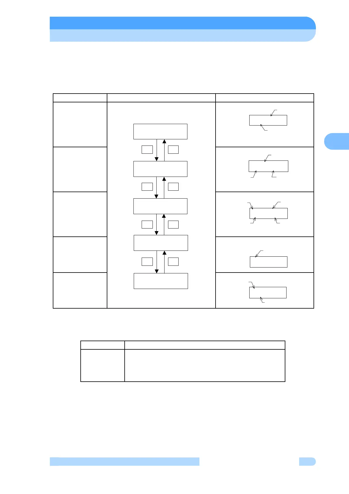
In the next tables, they are shown detailed flowchart of LCD display.
(1) MONITOR MODE
In monitor mode operation status of pump can be identified. If key DISPLAY is pushed in menu
mode, the LCD changes into monitor mode. The LCD changes automatically into monitor mode
after start or stop operation.
First, Monitor 2 display following to initial display after power switch turning on.
(Note 1) Operation Mode
Refer to Section 6.2 for details on changing the operation mode.
Mode Operation and LCD Display Description of Display
MONITOR 1
MONITOR 2
MONITOR 3
MONITOR 4
MONITOR 5
LCD Display Operation
LOCAL
REMOTE
RS-232C
RS-485
Control by a manual switch operation on the front panel
Control by a remote-control signal operation
Control by a RS-232C communication
Control by a RS-485 communication
STOP ROT= 0%
MC= 0.0A UB= 0%
OPERATION REMOTE
#####USER MEMO######
#####USER MEMO######
STOP ROT= 0%
+-
SZ= 0%
UB1= 0% UB2= 0%
SX1= 0% SY1= 0%
SX2= 0% SY2= 0%
+-
+-
+-
OPERATION REMOTE
#####USER MEMO######
USER MEMO
(Note 3)
Operation Mode
(Note 1)
#####USER MEMO######
STOP ROT= 0%
Pump Operation
Mode (Note 2)
Motor Rotational
Speed (Note 4)
USER MEMO
(Note 3)
STOP ROT= 0%
MC= 0.0A UB= 0%
Pump Operation
Motor
Rotational
Speed (Note 4)
Motor Current
Unbalance
Monitor Value
Mode (Note 2)
SX1= 0% SY1= 0%
SX2= 0% SY2= 0%
Magnetic Bearing
Sensor Input Value
X1,Y2,X2,Y2 Axis
SZ= 0%
UB1= 0% UB2= 0%
Magnetic Bearing
SensorInput
Value Z Axis
Unbalance Monitor
Value 1,2 Axis
 Loading...