A2. INTERFACE SPECIFICATION
A-5
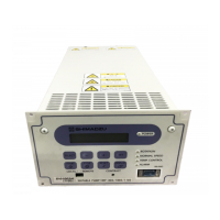
Power Supply Unit
INSTRUCTION MANUAL
A
A2.2 RS-485
A2.2.1 Transmission Specification
*1 : There may be restrictions depending on cable length or cable type. Perform appropriate
checks in the actual operating environment.
A2.2.2 Communications Connector
A2.2.3 CABLE
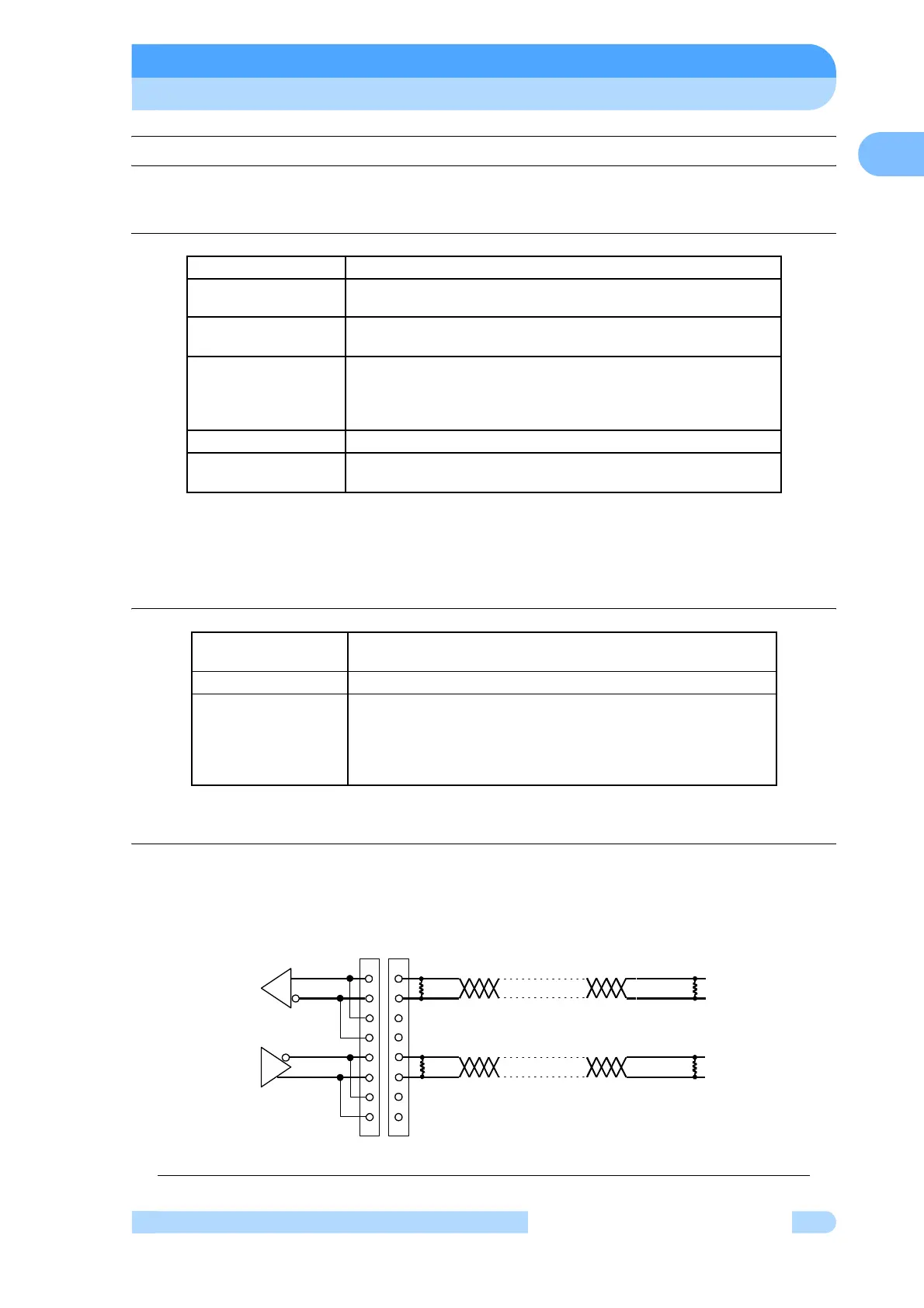
(1) Cable Connection
a. Multi-drop function OFF
Fig. A-2 Example of RS-485 cable wiring connections (Multi-drop function OFF)
Interface RS-485
Synchronous
system
Asynchronous
Transmission rate
1200, 2400, 4800, 9600 and 19.2k bits per second
(See Section 6.6 “Software Operation” (4) for settings).
Character
configuration
Start bit: 1
Data bits: 8
Parity: None
Stop bits: 1
Flow control None
Number of power
supply
Multi-drop function OFF: 1
Multi-drop function ON: Max 32 (*1)
Connector
Rear panel RS-485 connector
(See Section 2.1 “Power Supply Unit”).
Connector type D-Sub 9-pin Female, Screw lock size:M2.6
Pin assignment
1, 6 : RxA (Receive data +)
2, 7 : RxB (Receive data –)
3, 8 : TxB (Transmit data –)
4, 9 : TxA (Transmit data +)
* Other pins are not connected.
RXA
RXB
TXB
TXA
TXA
TXB
RXB
RXA
Power Supply Unit 1
Terminator on
COMPUTER
120Ω
120Ω
120Ω
120Ω
1
2
6
7
3
4
8
9
1
2
6
7
3
4
8
9
Cable connector
D-Sub 9pin Male