SECTION 6 OPERATION
58
263-13228
6
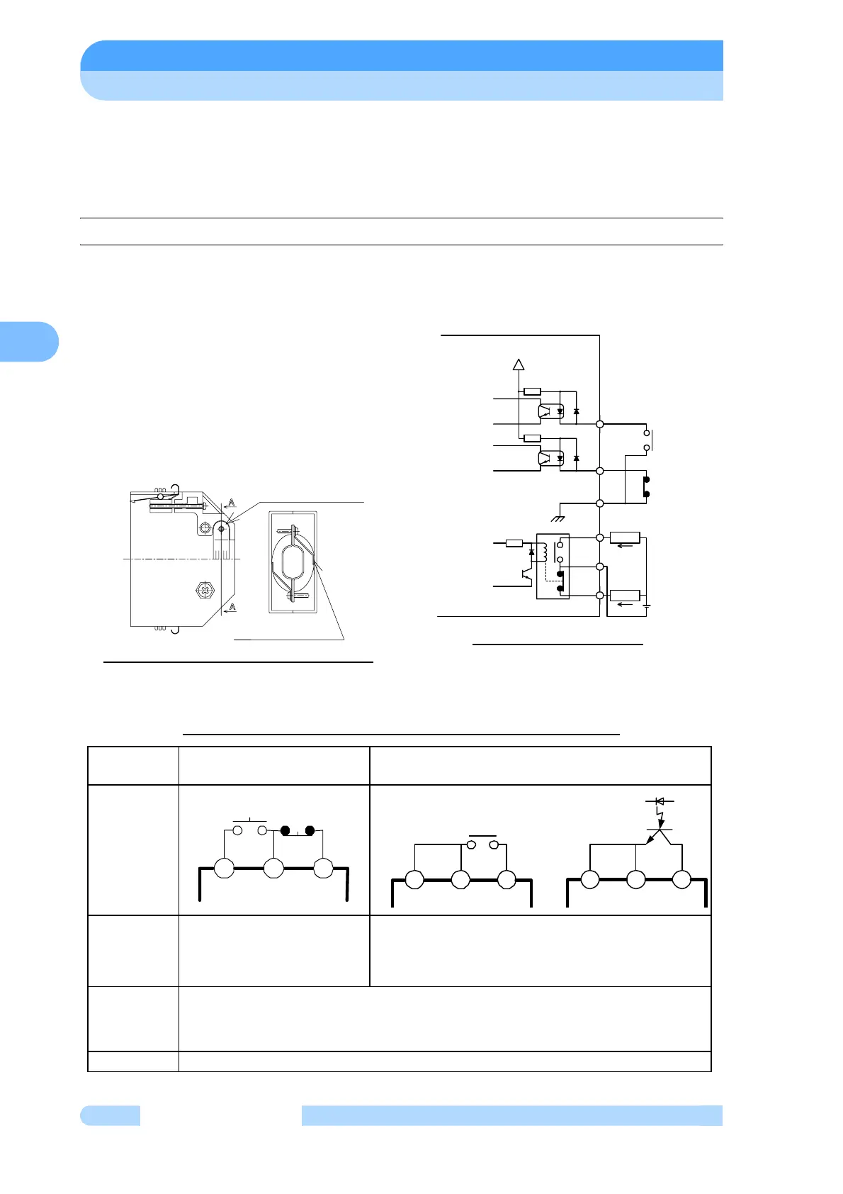
6.7 Remote-Control Connector
6.7.1 Specifications
Table 6-2 Start/Stop According to Remote-Control Signals
The controller is provided with remote-
control connector for connection with
remote operation, alarm signals, etc. Use
this connector and a cable with shield as
necessary. The shield of the cable should
be connect to case of Remote-connector.
(See Figs. 6-9, 6-10, 6-11 and Tables 6-2,
6-3) For remote-controlled operation, shift
the REMOTE/LOCAL selection switch (Fig.
2-3 (15)) to REMOTE mode in advance.Fig.
6-9 Remote-Control Connector
Fig. 6-8 Remote-Control Connector
Remote-Control Circuit
Connection
method
By momentary type START/
STOP switch
By alternate type switch
Wiring
connection
Starting
Pump start by short-
circuiting (15) and (14).
Pump stop by opening (16)
and (14).
Pump start, with the contact close or photo transistor
ON ((16) to (14) short-circuit)
Pump stop, with the contact open or photo transistor
OFF ((16) to (14) open)
Electric
capacity
[Contact] : It is connected to +12V circuit and subject to stable open-close of DC 5 V, 1mA.
Voltage...30VDC or more, Current...10mA or more
[Photo transistor ] : Select a photo transistor with a collector-emitter voltage limit of 30VDC
and an on-state collector current of 10mA or more.
Input rating Direct forward current 50mA; DC reverse voltage 5V
Make contact with the
connector housing
Grip the cable shield
with the clamp
1.2k
1.2k
+12
V
INSIDE OF POWER UNIT
LOAD
LOAD
IN
IN
GND
A
CONTACT
B CONTACT
a
b
c
<DC30V,1A
INPUT
CONTACTS
<DC30V,1A
15 14 16
15 14 16 15 14 16