SECTION 5 INSTALLATION
24
263-13228
5
5.3 Connection of the Pump to the Power Supply Unit
NOTICE
Insert straight the control cable connector after checking its key direction. Inserting it in oblique
direction would cause damage of the connector pins. After the insertion, turn the cable connector
clockwise until the rotation lock clicks.
NOTICE
Don't disconnect each cable while the pump is running. Particularly before disconnecting the
control cable, Check complete shutdown of the pump by ROTATION lamp goes out and,
thereafter, turn off the POWER switch.
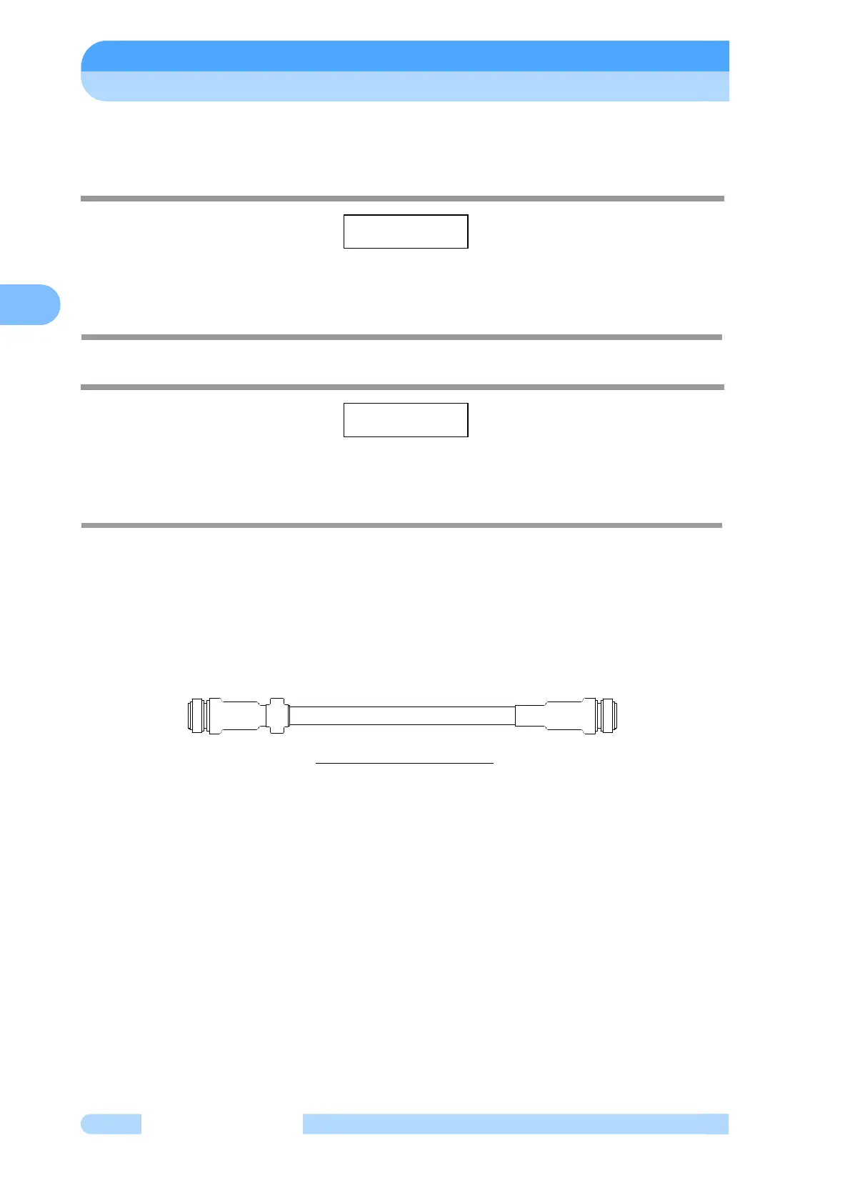
Control Cable:
Use the control cable that conformed CE marking. It has ferrite core at power supply side.
Control cables available for the use are identified with "262-75369A". But, If no ferrite core is not
fixed arround a control cable, it is not conformed CE marking.
Check that it is identified as specified. Even the use of other similar cable would disable start-
up of the pump, even though it could be connected. After turn on the POWER switch of the power
supply unit, ALARM lamp (Fig. 2-1 (14)) lights, if an old type cable is connected.
Fig.5-10 Control Cable
Connecting Sequence (See Fig. 2-2 and Fig. 5-10):
(1) Turn off the POWER switch (Fig. 2-2 (17)) on the rear panel of the power supply unit. Or
otherwise check that it is off.
(2) Connect the power supply unit to the control connector ( Fig. 2-2 (19)) of the pump proper
with the control cable.
(3) Connect the power supply unit to the motor connector ( Fig. 2-2 (20)) of the pump proper
with the motor cable.
(4) For remote operation of the turbo molecular pump or intake of status signal, etc., connect
the RS-485 connector (Fig. 2-2 (21)) or RS-232C connector (Fig. 2-2 (22)), Remote-Control
connector (Fig. 2-2 (23)). When using Remote-Control connector, make wiring connection
as instructed in Section 6.7 "Remote-Control Connector".
All interfaces are SELV(Safety extra-low Voltage).
SHIMADZU 262-75369A