6.7 Remote-Control Connector
61
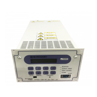
Power Supply Unit
INSTRUCTION MANUAL
6
.
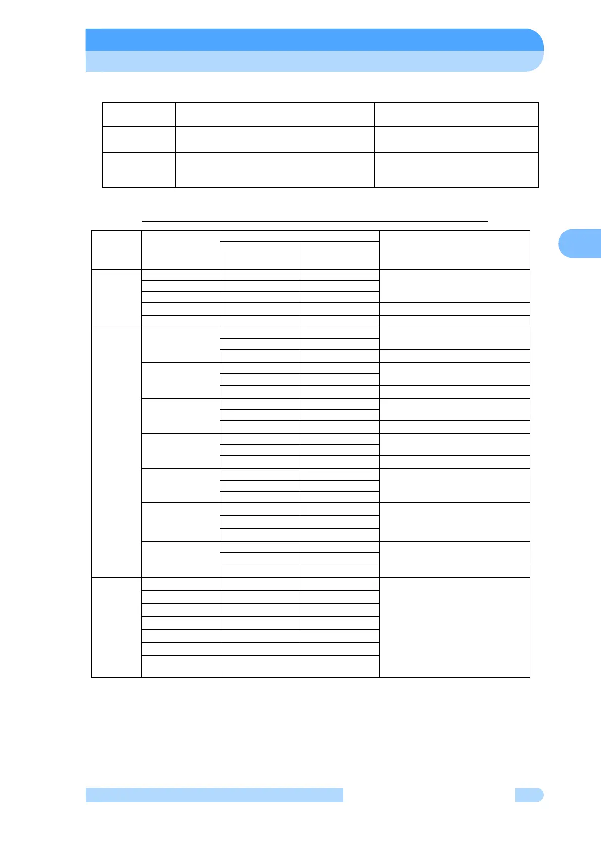
Table 6-4 Pin Configuration Comparison Chart (Default Settings)
(Note 1) To avoid the risk of fire, please remove wiring, if wiring of power supply for the
transistor output is connected to the pin.
Power Supply
Unit
ALARM Signal REMOTE Signal
EI-xx03M/MD
When the power supply is turned off, the
ALARM signal is off.
Remote signal is forcibly off during
regenerative braking.
EI-Dxx03M
SEMI E74
Settings
When the power supply is turned off, the
ALARM signal is on.
Remote signal during regenerative
braking depends on the control mode.
Signal Type Signals
Pin numbers
Compatibility
EI-xx03M/MD
EI-Dxx03M
(EI-03Compatible
Mode)
INPUT START 15 15 Same pin number, same function
STOP 16 16
RESET 17 17
LOW SPEED 33 Variable rpm input added
GND(COMMON) 14 14 Same pin number, same function
OUTPUT1
(Relay Out-
put)
ROTATION 29:Make contact 29:Make contact Same pin number, same function
30:Common 30:Common
4 :Break contact “Break contact” added
NORMAL 25:Make contact 25:Make contact Same pin number, same function
26:Common 26:Common
2 :Break contact “Break contact” added
ACCELERATION 23:Make contact 23:Make contact Same pin number, same function
24:Common 24:Common
1 :Break contact “Break contact” added
BRAKE 27:Make contact 27:Make contact Same pin number, same function
28:Common 28:Common
3 :Break contact “Break contact” added
ALARM 21:Make contact 21:Make contact Same pin number, same function
22:Common 22:Common
20:Break contact 20:Break contact
WARNING 11:Break contact Added function
13:Common
12:Make contact
REMOTE 31:Make contact 31:Make contact Same pin number, same function
32:Common 32:Common
5 :Break contact “Break contact” added
OUTPUT2
(Transistor
Output)
MOTOR 3 Removed function
EI-Dxx03M units have a pin assigned
to the “Break contact” output terminal
of OUTPUT1
(If wiring is connected to the pin for
EI-xx03M/MD units and is used with-
out modification, a malfunction could
occur on the system controller side,
so please remove it.)
MAG.BEARING 4
POWER FAILURE 5
PUMP TEMP. 7
CONT. TEMP. 8
V(+) (Note 1) 1
COM(-) (Note 1) 2