Copyright © Shimmer 2017
Realtime Technologies Ltd Shimmer User Manual
All rights reserved Rev3p
17
For further hardware-based information on the microSD card socket, please refer to Section 6.2.2 of
this manual. For information on firmware solutions for using the microSD card please refer to
Section 5.1 of this manual.
Note: The Shimmer is not compatible with SDHC cards.
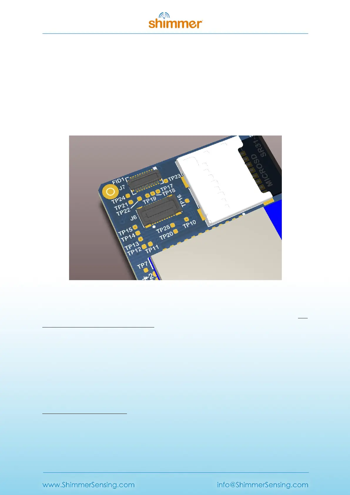
3.1.6. Internal Connector
The expansion connector is on the top side of the Shimmer and consists of both J6 and J7, as shown
in Figure 3-2. It is used to connect to internal daughter boards. All expansions will include
appropriate enclosures.
Figure 3-2 Shimmer3 mainboard's internal expansion connector
Care should be taken when making decisions about hardware configuration, in order to minimise the
number of times that boards are removed from and inserted into the internal connector. The
connector is rated for up to four insertions.
2
Never force the expansion board when connecting it to the Shimmer mainboard and be sure to
install it with the board aligned with dimensions of the Shimmer PCB. The connection is keyed and
its orientation is visually obvious. The expansion enclosure may be self-aligning to assist in the
assembly process.
For further hardware-based information on the internal connector please refer to Appendix A -
Mainboard detail for Debug and Testing.
2
Since September 2014, all expansion modules sold by Shimmer are permanently fixed to the Shimmer3
mainboard. Removal of the expansion board from the mainboard should not be carried out under any
circumstances. Doing so will cause damage to one or both of the boards and any necessary repairs will not be
covered by warranty.