Copyright © Shimmer 2017
Realtime Technologies Ltd Shimmer User Manual
All rights reserved Rev3p
40
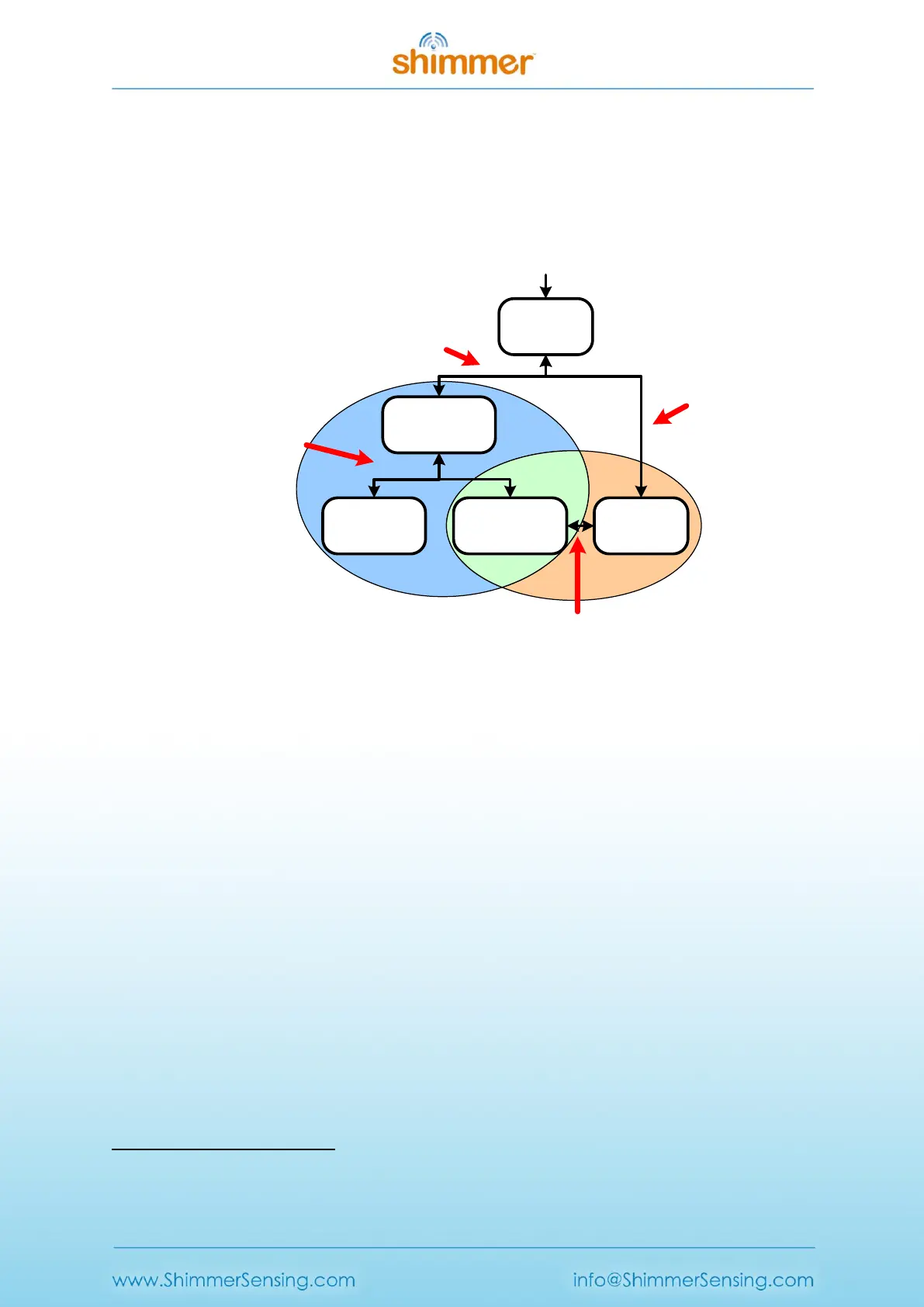
A Shimmer3 programmed with LogAndStream firmware can be in one of five states: Idle, BT
Connected, BT Streaming, BT Streaming + SD Logging or just SD Logging - as shown in Figure 5-1. The
active states form two operational branches from which the user can choose to operate the
Shimmer3 device - one initiated by a Bluetooth connection (blue shaded area in Figure 5-1) and the
other based on SD Logging operation (orange shaded area in Figure 5-1).
BT
Connected
Idle
BT
Streaming
BT Streaming
+ SD Logging
SD
Logging
(b) Initiated by
host application
or a short button
press
(a) Bluetooth connect/
disconnect by host
application
(c) Short button
press
(d) Bluetooth connect/disconnect by host
or disconnect when out-of-range
Bluetooth
activity
SD card
activity
Power on / Reset
Figure 5-1 LogAndStream firmware operational hierarchy.
LogAndStream firmware LED Indicators
The Shimmer3 has five LEDs in two locations as shown in Figure 2-1: the lower LED location (location
A) which contains the green (b), yellow
5
and red LEDs; and the upper LED location (location B) which
contains the green (a) and blue LEDs.
The two upper LEDs are used to indicate state of operation for the LogAndStream firmware. The
status of each depends on whether the Shimmer3 is in a docked or undocked state, as shown in
Table 5-1 below.
5
Note that what is referred to as the yellow LED may appear orange to some users.