④ Video codec connection to far end
Connect the codec to the appropriate network to connect with the far end.
⑤ Audio from far end to amplifier
Route the far end audio through the video codec audio output to an amplifier.
⑥ Amplified audio signal to loudspeakers
Connect the loudspeakers to the amplifier to deliver the audio from the far end.
Installation
Microphone Placement
Room Variables
Optimal microphone placement is determined by the seating arrangements and infrastructure. Follow these guidelines for the best possible results:
• In rooms with flexible furniture arrangements or multiple array microphones, use the microphone configuration tool in the web application to ensure that the
coverage is adequate for all seating scenarios.
• The lobes should be pointed towards the front of each talker. Carefully consider placement in rooms where talkers may face a screen during a video conference.
• Avoid installing the microphone directly next to unwanted sound sources, such as air vents or noisy video projectors.
• Consider installing acoustic treatment to improve speech intelligibility in rooms that are too reverberant.
Mounting Height
The maximum mounting height that can be set in the ceiling array microphone web application is 30 feet (9.14 meters). In a typical acoustic environment1, the
microphone maintains an "A" rating based on the STIPA2 (Speech Transmission Index for Public Address systems) international standard at distances up to
16 feet between the microphone and talker. In better acoustic environments, the STIPA "A" rating may extend beyond 16 feet.
Consider the following when determining a mounting height:
• The pickup pattern of the ceiling array is narrower than a shotgun microphone, and therefore it can be placed farther from the source than any other microphone.
While the web application shows an ideal coverage zone for each channel, keep in mind that there is no specific barrier at which the audio degrades or
gates off. Lobe sensitivity data is available for each width setting in the product specifications.
• Like all microphones, tonality changes as the distance from the source increases.
• The intelligibility scale helps to predict how the microphone will sound at a given height.
• The coverage area of the lobes increases at farther distances.
[1] Room conditions: RT60 (reverb time) = 500 ms @ 1kHz, A weighted room noise = 40dBSPL(A)
[2] IEC-602682-16 standard
Intelligibility Scale
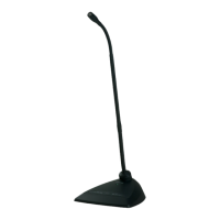
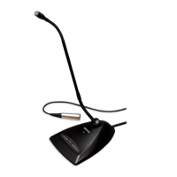
The intelligibility scale objectively compares the acoustic performance of the array microphone with a cardioid gooseneck microphone at various distances. This
information is useful for predicting how the array microphone will perform at a given distance and to determine an ideal mounting height. The data in the intelli-
gibility scale table is derived from measuring the microphones to meet an equivalent value from the Speech Transmission Index IEC-602682-16 standard.
Distances With Equivalent Speech Transmission Index Values
Cardioid Gooseneck Microphone (Distance to Talker)Ceiling Array Microphone (Distance to Talker)
3.75 feet (1.14 m)6 ft (1.83 m)
5 feet (1.52 m)8 ft (2.44 m)
6.25 feet (1.91 m)10 ft (3.05 m)
7.5 feet (2.29 m)12 ft (3.66 m)
Data was collected in a typical huddle room with the following measurements:
• Reverberation decay time: 500 ms @ 1kHz
• Noise floor: 40 dB SPL (A-weighted)
Note: These values are specific to the described room. In a well-controlled acoustic environment, the array microphone may perform with equivalent Speech
Transmission Index values at even greater distances. In highly reverberant rooms, the performance is less predictable.
A = Distance between array microphone and talker
Shure IncorporatedMXA910 Ceiling Array Microphone
2017/10/1814/57