14.6.3 Connecting supply voltage for the device in CDM420-0001
Device = CLV61x-xx0xxx (serial variant)
Device
3CDM420-0001
V
S
1
5
5
Shield
1 +24 V
2 GND
+24 V*
GND
S1
F
Shield
GND
.
.
.
.
.
.
ON
OFF
S1 : POWER
+24 V*
POWER
V
S
GND
V
S
- +24 V -
F
S 1
- +24 V*
4
V
s
1
110
15
6
11
5
Cable 2
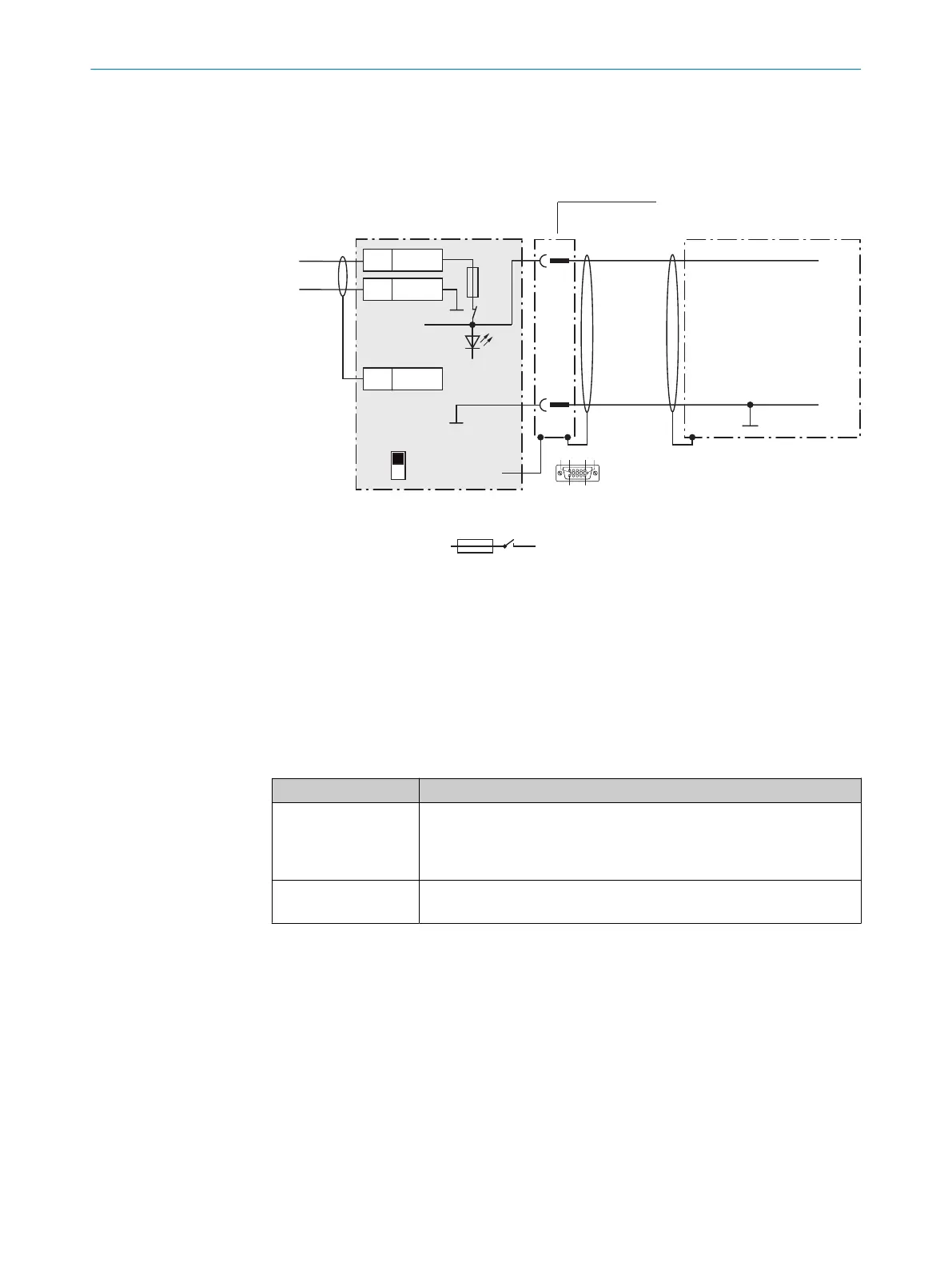
Figure 53: Connecting supply voltage for the device in CDM420-0001 connection module.
1
Supply voltage V
S
2
Connecting cable permanently connected with the device (male connector, D-Sub-HD,
15-pin)
3
Device
4
Connection module: female connector, D-Sub-HD, 15-pin
Function of switch S1
Table 34: Switch S1: Power
Switch setting Function
ON Supply voltage +24 V connected to CDM420-0001 and device via fuse
and switch S1 as supply voltage +24 V*
Supply voltage +24 V* can be additionally tapped at terminals 29 and
39
OFF CDM420-0001 and device disconnected from supply voltage
Recommended setting for all connection work
14.6.4 Wiring serial host interface RS-232 of the device in the CDM420-0001
Device = CLV61x-xx0xxx (serial variant)
14 ANNEX
90
O P E R A T I N G I N S T R U C T I O N S | CLV61x 8017840/19OF/2021-10-28 | SICK
Subject to change without notice
 Loading...