Pin Signal Function
3 RD+ (Ethernet) Receiver+
4 RD– (Ethernet) Receiver
Connection for POWER (CLV61x-Dx41x)
Figure 21: Male connector, M12, 4-pin, A-coded
Pin Signal Function
1 V
s
Supply voltage
2 Reserved (Do not use.)
3 GND Ground
4 Reserved (Do not use.)
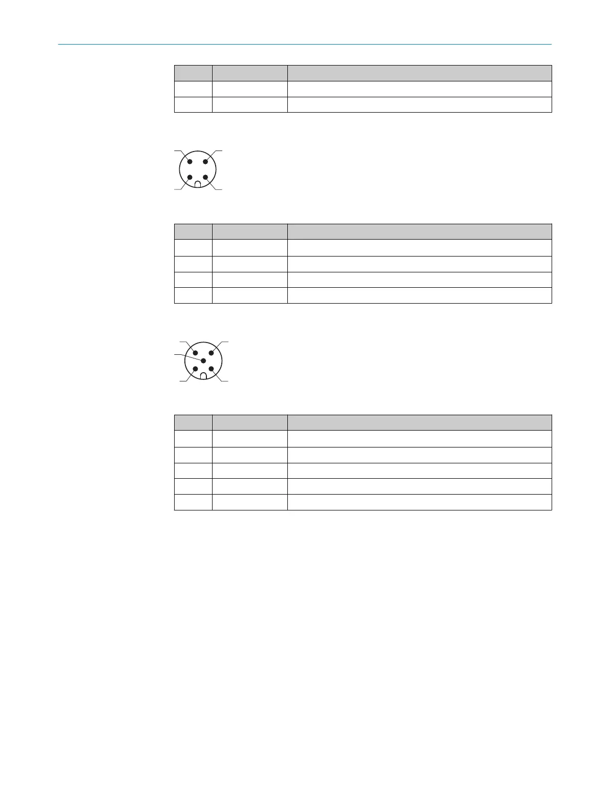
POWER and trigger input connection (CLV61x-Dx52x)
Figure 22: Male connector, M12, 5-pin, A-coded
Pin Signal Function
1 V
s
Supply voltage
2 Reserved (Do not use.)
3 GND Ground
4 Reserved (Do not use.)
5 Sensor 1 Digital switching input for external reading cycle
6.4.1 Wiring the PROFINET interface
1. Connect the device using the pre-assembled cables to the left and right of the
additional devices (IO devices) in the PROFINET network. Line or ring topology is
possible. If only one Ethernet connection is needed (e.g., last device in a line topol‐
ogy), either the P1 or P2 connection can be used. Fit a protective plug onto the
unused connection (as in delivery condition).
2. Switch on the supply voltage for the device. The device starts with a delay and
uses the default parameters set in the factory for the initialization. After a suc‐
cessful self-test, the blue LED on the device lights up to indicate the "Device
Ready" status.
ELECTRICAL INSTALLATION 6
8017842/ZOK7/2019-02-01 | SICK O P E R A T I N G I N S T R U C T I O N S | CLV61x DualPort (PROFINET)
39
Subject to change without notice
 Loading...


