– Alignment of the device in the x and y axes can be adjusted.
– The mounting device must be able to bear the weight of the device and con‐
necting cables without shock.
– The housing must be thermally isolated from the bracket for devices with
heating. To do so, attach appropriate plastic insulating slabs to the fixing
screws between the housing and the bracket.
■
Two or three M5 screws for mounting the device
– The screw length depends on the wall thickness of the mounting device.
– The maximum screw in depth in the device is 5 mm from the housing sur‐
face.
5.3 Mounting location
When selecting the mounting location, the following factors are significant:
•
Basic allocation of the scan line to the bar code.
•
Reading distance to the bar code and aperture angle α
•
Angular alignment of the device
•
Avoidance of surface reflections
•
Count direction of the reading angle (position of the bar code along the scan line)
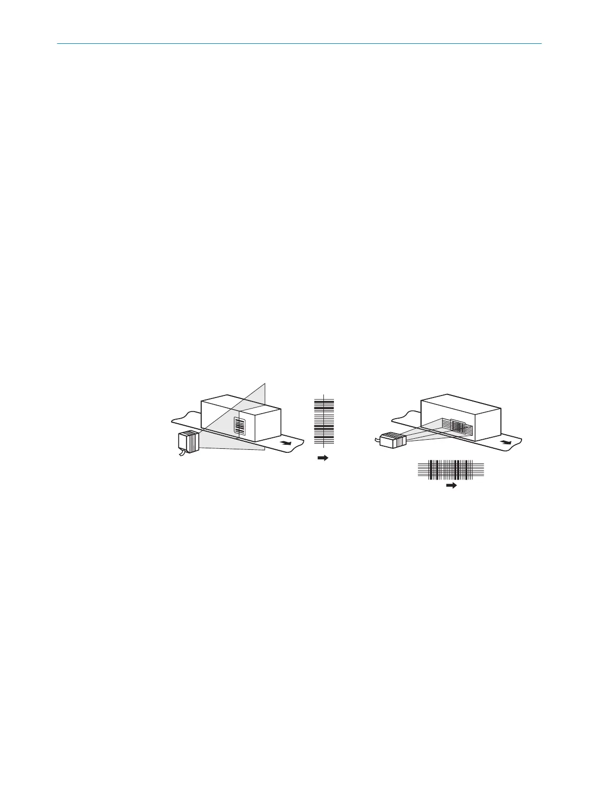
5.3.1 Basic allocation of the scan line to the bar code
The basic allocation of the scan line to the bar code on the object depends on the ver‐
sion of the device (line scanner or grid scanner).
line scanner raster scanner
1 2
Figure 11: Allocation of scanning line(s) to bar code and conveyor direction
1
Line scanner
2
Grid scanner
5.3.2 Reading distance to the bar code and aperture angle α
The maximum distance from the reading window of the device to the bar code may not
exceed the design values for the device. Because of the V-shaped deflection of the
beams, the usable length of the scan line for evaluation (reading field height) depends
on the reading distance.
MOUNTING 5
8017842/ZOK7/2019-02-01 | SICK O P E R A T I N G I N S T R U C T I O N S | CLV61x DualPort (PROFINET)
29
Subject to change without notice
 Loading...


