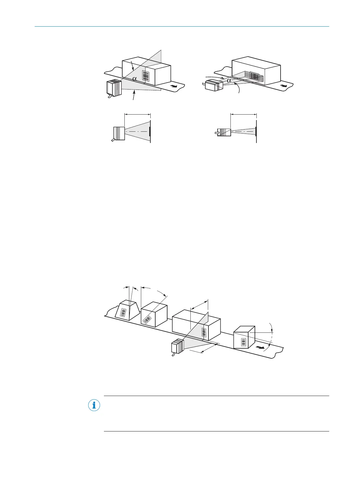
line scanner raster scanner
reading distance reading distance
1 2
3
3
Figure 12: Definition of the reading distance and the aperture angle α
1
Line scanner
2
Grid scanner
3
Reading distance
In the specification diagrams (see "Reading field diagrams", page 58), the height of
the reading field is shown as a function of the reading distance for differing resolutions
(module widths).
5.3.3 Angle alignment of the device
The optimum alignment of the device is achieved when the scan line crosses the
stripes of the bar code as close to a right angle as possible (tilt and inclination). Possi‐
ble reading angles that can arise between scan line and bar code at all three levels in
the area must be taken into account.
In order to prevent surface reflections, the angle of rotation must be approx. 15° out of
plumb to the bar code, see "Avoidance of surface reflections", page 31.
Figure 13: Line scanner: Read angle occurring between scanning line and bar code
1
Depth of field
2
Reading distance
NOTE
The specified maximum values can only be reached in optimum conditions. The actual
maximum depends on module width, code type, print contrast, ambient light, distance
and scanning frequency.
5 MOUNTING
30
O P E R A T I N G I N S T R U C T I O N S | CLV61x DualPort (PROFINET) 8017842/ZOK7/2019-02-01 | SICK
Subject to change without notice
 Loading...


