7.3 Adjust the device
For complete adjustment of the device, the electrical installation must be complete and
the device must have been commissioned.
1. Loosen the bracket screws so that the device can be aligned.
2. Align the device so that the angle between the scanning line and the bar code
stripes is almost 90°.
3. To prevent interference reflections, arrange the device as close to being plane-par‐
allel to the object surface as possible.
4. Manually place objects with bar codes one after the other into the reading range
of the device, see "Technical data", page 55.
5. Check the reading result with the SOPAS ET configuration software.
6. When doing so, place objects at different positions (angles) in the reading field
and ensure that the limit values for the permitted reading angles are not
exceeded, see "Angle alignment of the device", page 30.
7. Align the device so that the good read rate is between 70% and 100%.
8. Tighten the screws on the device.
7.4 Initial commissioning
The device is adjusted to the application situation on site using the SOPAS ET configura‐
tion software on the PC. The default factory settings of the device are the starting point
for this. Their parameter values (configuration data) can be adapted in the working
memory of the device for optimization purposes. To do so, the user creates an applica‐
tion-specific parameter set with the SOPAS ET configuration software or changes the
set later as required. The user then loads the current parameter set to the permanent
parameter memory of the device.
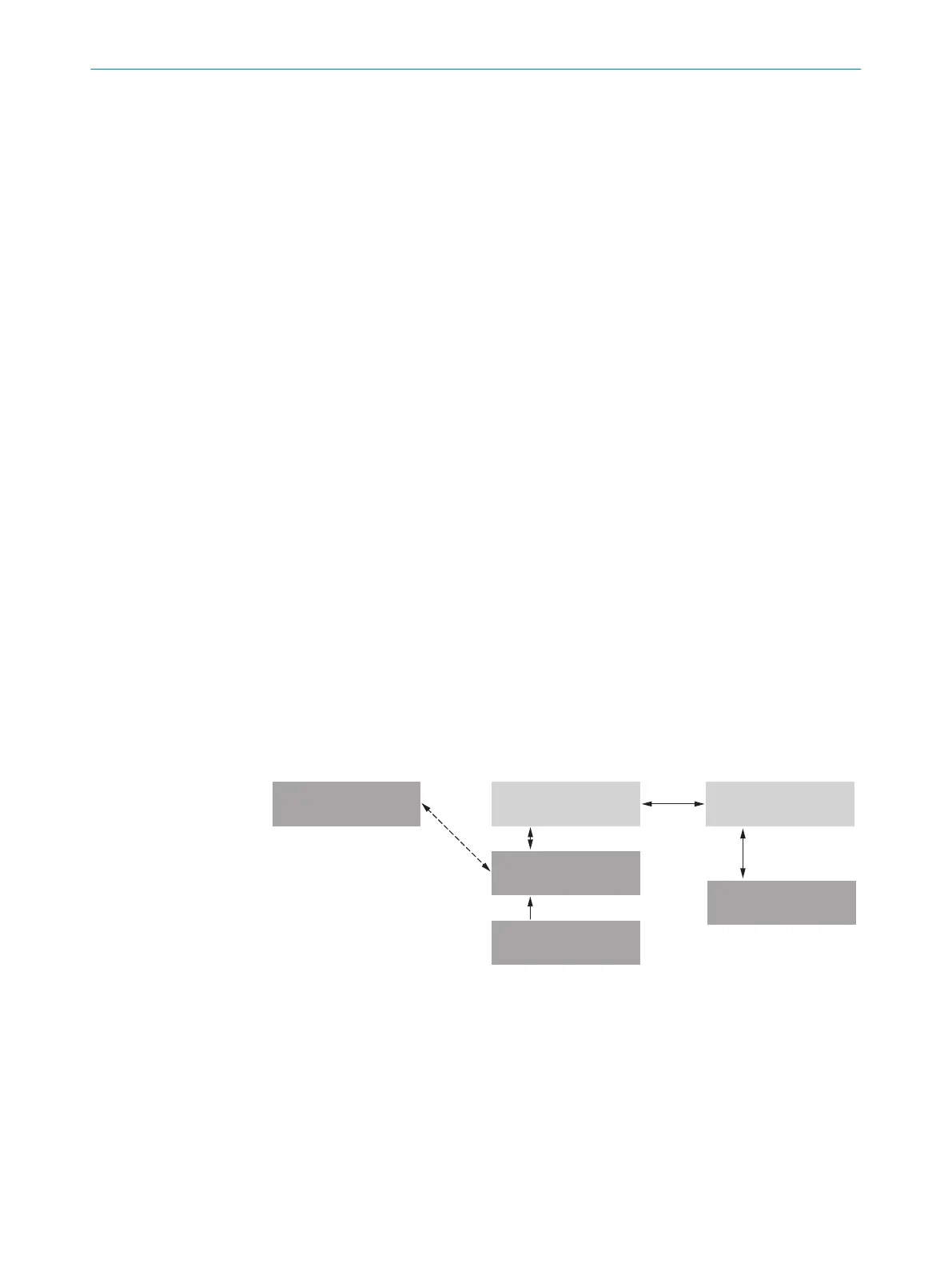
Memory organization for parameter set
The following diagram shows the memory management principle for the involved inter‐
nal and external components:
Parameter set in the
main memory of the
device 6
Permanently saved
parameter set of the
device 5
Factory default setting of
the device 7
Device 2Optional: 1 PC with SOPAS ET
Configuration Software 3
MicroSD memory card 4
Volatile memory à
Opened project file
with current parameter
set of the device 8
Volatile memory à
Non-volatile memory ß
Non-volatile memory ß
Saved project file (*.sopas)
with archived parameter
set of the device 9
Data base on e. g. hard drive
(non-volatile memory) á
Permanently saved
parameter set of the
device 5
Non-volatile memory ß
Figure 26: Configuring with SOPAS ET and saving the parameter set
1
Optional (only CLV61x-DxxXxx, with X= 3 or 4)
2
Device
3
PC with SOPAS ET configuration software
4
MicroSD memory card
5
Permanently saved device parameter set
6
Parameter set in the working memory of the device
7
Factory-set defaults for the device
8
Opened project file with current device parameter set
COMMISSIONING 7
8017842/ZOK7/2019-02-01 | SICK O P E R A T I N G I N S T R U C T I O N S | CLV61x DualPort (PROFINET)
43
Subject to change without notice
 Loading...


