•
CRLF protocol type:
The data fields are completed by the non-displayable ASCII characters <CR>
(0x38) and <LF> (0x35). These also act as separators in the data stream.
•
STX/ETX protocol type:
The data fields are integrated in the non-displayable ASCII characters <STX>
(0x02) and <ETX> (0x03). The first four characters of the data field have a con‐
stant pre-assignment for compatibility reasons.
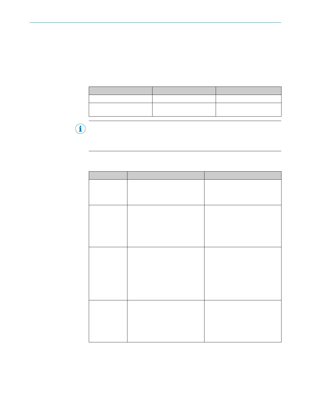
Table 10: Protocol structure and output mode
Protocol type Protocol structure (example) Output mode
CRLF
<Data field><CR><LF>
Continuous
STX/ETX
<STX><data
field><ETX>
Continuous
NOTE
Non-volatile storage is possible for the selected protocol type and the mode for continu‐
ous output. The device then automatically begins continuous data output according to
the saved settings after switching on, see "Special functions", page 24.
The following data can be output via the continual output:
Table 11: Data for continuous output
Designation CRLF protocol structure STX/ETX protocol structure
Distance (resolu‐
tion according to
setting)
<[sign]><7*[0...9]><CR><LF
>
Example +1,800 mm:
+0001800<CR><LF>
<STX>0322<[sign]><7*[0...9
]><ETX>
Example +1,800 mm:
<STX>0322+0001800<ETX>
Distance + speed
(resolution of dis‐
tance + speed
according to set‐
ting)
<[sign]><7*[0...9]><[sign
]><5*[0...9]><CR><LF>
Example +1,800 mm or
+2,000 mm/s:
+0001800+02000<CR><LF>
<STX>0324<[sign]><7*[0...9
]><[sign]><5*[0...9]><ETX>
Example +1,800 mm or
+2,000 mm/s:
<STX>0324+0001800+02000<ET
X>
Distance + status
Status double
word is coded in
hexadecimals:
32 Bit (8 ASCII
character), struc‐
ture "Trou‐
bleshooting",
page 92
<[sign]><7*[0...9]>_<8*[0.
..F]><CR><LF>
Example +1,800 mm or status bit
20, 15, 14 and 8 active:
+0001800_0010C100<CR><LF>
<STX>0321<[sign]><7*[0...9
]>_<8*[0...F]><ETX>
Example +1,800 mm or status bit
20, 15, 14 and 8 active:
<STX>0321+0001800_0010C100
<ETX>
Distance + signal
level (RSSI)
<[sign]><7*[0...9]>_<5*[0.
..9]><CR><LF>
Example +1,800 mm or 2,300 dig‐
its:
+0001800_02300<CR><LF>
<STX>0323<[sign]><7*[0...9
]_<5*[0...9]><ETX>
Example +1,800 mm or 2,300 dig‐
its:
<STX>0323+0001800_02300<ET
X>
The following table shows the maximum possible output rate for continuous data out‐
put depending on the data transmission rate, protocol and scope of the output data. If
needed, this output rate can be reduced via the “RS-422 output cycle time” parameter.
PRODUCT DESCRIPTION
3
8019329/12TZ/2019-03-28 | SICK O P E R A T I N G I N S T R U C T I O N S | DT1000 and DL1000
21
Subject to change without notice
 Loading...


