Table 115: Valid sequence for muting sensor input signals with sequence monitoring
Direction detection Valid sequence for muting sensor input signals
Forward A1 before A2 before B1 before B2
Backward B2 before B1 before A2 before A1
Deviations from the sequence result in a muting error, which is indicated at the Mut
ing
error output. This applies both to the sequence of activation (muting sensor signal
inputs switch from 0 to 1) and to deactivation (muting sensor signal inputs switch from
1 to 0).
Complementary information
•
If there are objects in the area of the muting sensors during the first logic cycle
and therefore one or more muting sensor signal inputs are set to 1, this gener‐
ates a muting error. The signaling of the error state at the Muting error output is
suppressed if the BWS input = 1. Before a new valid muting cycle can be executed,
this error must be reset.
•
The muting times have an accuracy of ± 10 ms (evaluation plus logic execution
time).
Further topics
•
"Safety notes for muting applications", page 18
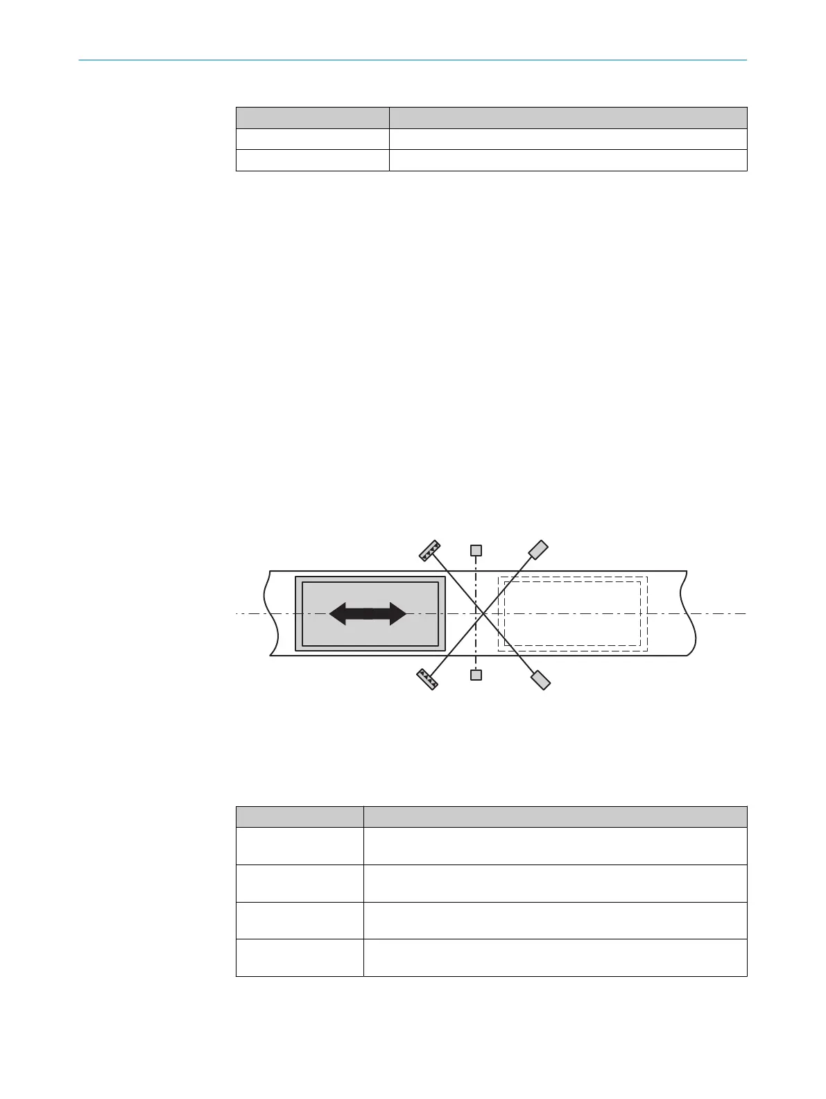
7.6.2.7.3 Cross muting V1
Overview
Figure 48: Muting with a sensor pair arranged crosswise (A1 / A2)
Principle of operation
T
able 116: Inputs
Input Description
ESPE Data type: Boolean
T
he input must be connected to the electro-sensitive protective device.
A1
A2
Data type: Boolean
S
ignal from the muting sensor
Override
(opt
ional)
Data type: Boolean
"Input Override", page 100
Band signal
(opt
ional)
Data type: Boolean
"Input Band signal", page 103
7 CONFIGURATION
98
O P E R A T I N G I N S T R U C T I O N S | Flexi Compact 8024589/2020-11-10 | SICK
Subject to change without notice