"dsl_out"
"dsl_in"
"dsl_en"
Based on RS-485 specification, see appli‐
cation schematics
Typical signal transmission rate 9,375,000 baud
Drive interface
"online_status_d(15:0)"
"hostd_a(6:0)"
"hostd_di(7:0)"
"hostd_do(7:0)"
"hostd_r"
"hostd_w"
"hostd_f"
drive interface signals
SPI PIPE interface - optional, configurable by the user
"pipipe_clk"
"pipipe_miso"
"pipipe_ss"
Based on SPI specification
Maximum SPI clock 10 MHz
Control signals
Digital input – "sync" Synchronization to drive clock
Sync signal cycle time 12.2 … 1950 μs
Minimum sync signal duration 40 ns
Maximum jitter sync frequency ± 2 system clock cycles, 26 ns
Digital output – "sync_locked" Drive clock synchronization indicator
Digital output – "interrupt" Interrupt configurable by the user, high
active
Digital output – "link" DSL interface indicator, high active
Digital output – "fast_pos_rdy" Indicator fast position value availability
Digital output – "dev_thr_err" Indicator position estimator deviation
threshold crossed
Digital input – "bigend" Byte sequence selection for register
addresses
Test signals
Digital output “estimator_on” Indicator for active position estimator
Digital output “safe_channel_err” Indicator for safety frame transmission
errors
Digital output “safe_pos_err” Indicator for safe position update errors
Digital output “acceleration_err” Indicator for transmission error of fast
position
Digital output “acc_thr_err” Indicator for crossing of fast position error
counter threshold
Digital output “encoding_err” Indicator for 8b/10b encoding transmis‐
sion fault
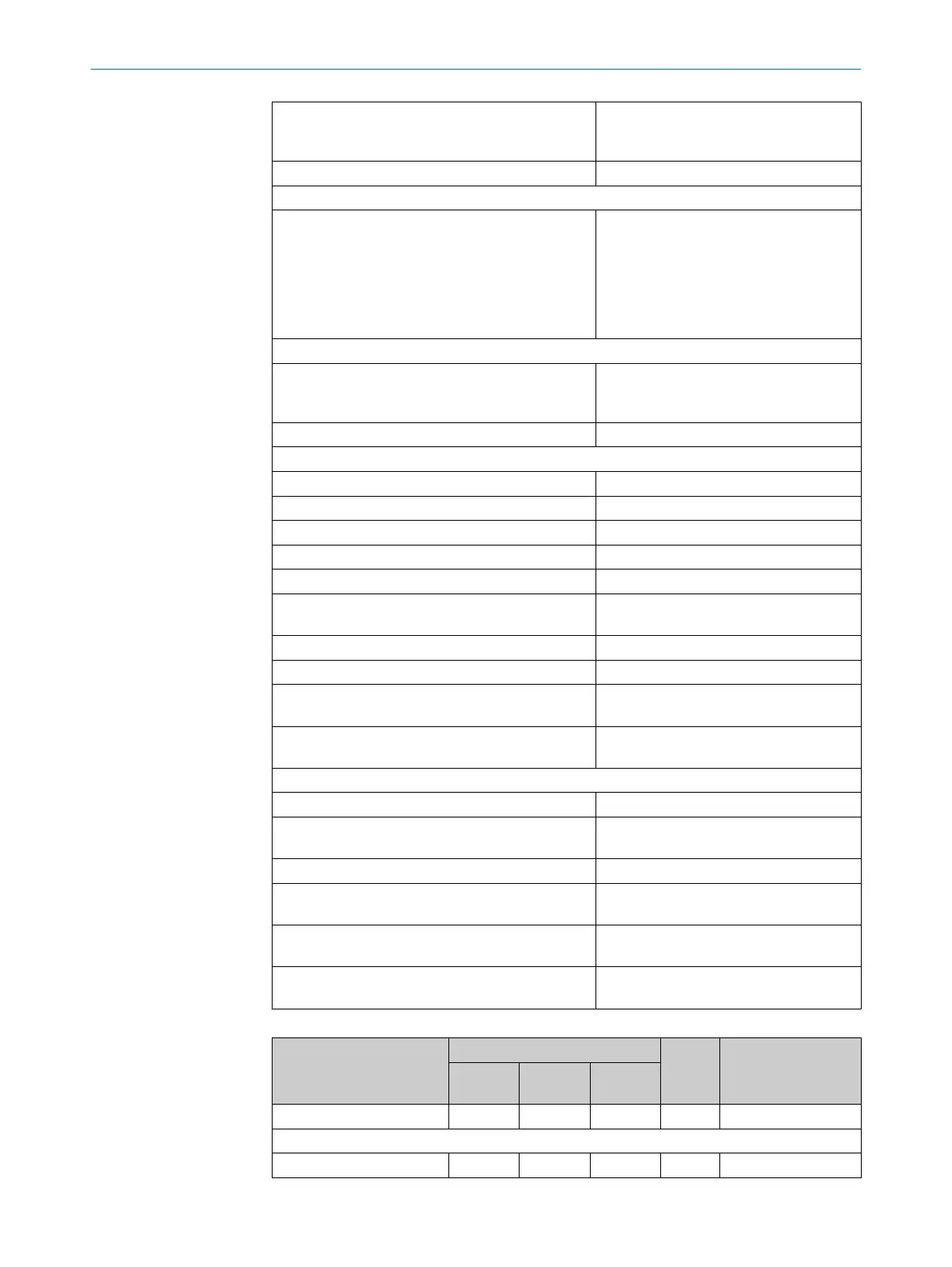
Table 185: Functional characteristics of the DSL Master IP Core
Parameter
Value
Units Remarks
Minimum Typical
Maxi‐
mum
System clock 74.9925 75.0000 75.0075 MHz ± 100 ppm
Characteristics of the interface
Wire transmission rate 9.375 MBd
FPGA IP-CORE 9
8017595/ZTW6/2018-01-15 | SICK T E C H N I C A L I N F O R M A T I O N | HIPERFACE DSL
®
137
Subject to change without notice
 Loading...


