ENGLISH
Siemens AG 610.40 064.01
13
2.1.2.2 Worm gear
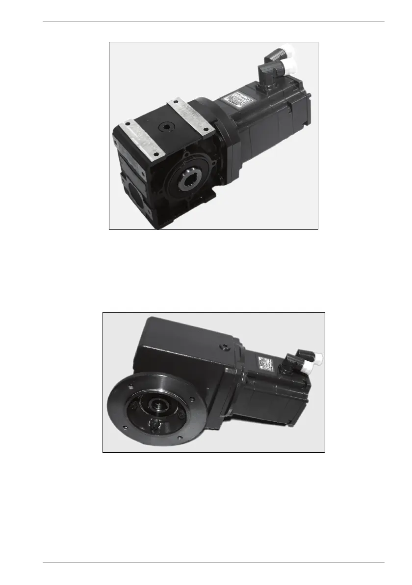
Fig. 1 Motor with worm gear (example)
Worm gear/motors are constructed in block design, and have one or two spur gear stag-
es (2 or 3 stage gear) upstream of the worm unit. The output shaft outputs at an angle of
90° to the input shaft. The worm unit has a hardened, ground steel worm and bronze
worm wheel, it dampens impacts and shocks. The teeth have a narrow flank clearance.
2.1.2.3 Bevel wheel gear
Fig. 2 Motor with bevel wheel gear (example)
Bevel wheel gear/ motors are constructed in block design.
The gear sizes K2 to K4 not only have the bevel wheel stage but also one or two up-
stream spur gear stages (2 or 3-stage gear). Sizes K5 to K10 not only have the bevel
wheel stage but are also equipped with one downstream and one or two upstream spur
gear stages (3 or 4-stage gear). The output shaft is arranged 90° offset from the drive
shaft. The curved tooth bevel wheel stage allows a narrow flank clearance.

 Loading...


