ENGLISH
12 610.40 064.01 Siemens AG
2 Product information
2.1 Product description
2.1.1 General information
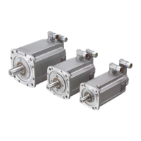
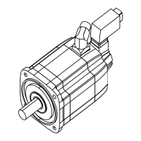
The geared motors consist of a three-phase servomotor (1FK7.) with a
flange-mounted gearbox. The three-phase servomotors are supplied with mounted gear-
boxes. Some models are supplied with an additional clutch.
The three-phase servomotor may be combined with all the gears / motor adapters
(clutches) described. The configuration (selection of the combination of three-phase ser-
vomotor and gear/clutch) has to be user-related to achieve this.
Three-phase servomotors (1FK7.) are permanent magnet excited, three-phase synchro-
nous
motors (three-phase servomotors) for operating with motor-controlled indirect a.c. con-
verters according to the sinusoidal current principle. The motors are intended for driving
and positioning machine tools, production machines, robots and handling devices.
2.1.2 Gears
2.1.2.1 General information
There are various models and designs of gears.
The gearing down stages reduce the usually high input speed to the desired lower output
speed. The input torque is multiplied by the ratio to the output torque (reduced by a slight
efficiency loss in the gear).
Design with Types of construction Gear shaft types
Worm gear and bevel
wheel gear
- Circle of tapped holes
- Flange design
- Foot mounting construction
and circle of tapped holes
- Foot mounting construction
and flange design
- Solid shaft with key
- Hollow shaft with a
keyway
- Hollow shaft with shrink
disk
Flat gear - Flange design
- Circle of tapped holes
- Solid shaft with/without
key
- Hollow shaft with a
keyway
- Hollow shaft with shrink
disk
Circular gear - Foot mounting construction
- Circle of tapped holes
- Flange design
- Foot mounting construction
and circle of tapped holes
- Foot mounting construction
and flange design
- Solid shaft with/without
key
NOTE
See the type plate for the particular design and mounting position.
The quantity of lubricant to fill (quantity of oil) depends upon the position in
which the gearbox is mounted, and is stated on the type plate.

 Loading...


