Mounting
Application Module FM 458-1 DP - User Manual 3-3
A5E01078222-02 Edition 03.2009
There is a 5 x 24-pin socket to connect expansion modules to the LE bus.
They are provided on the right-hand side of the FM 458-1 DP application
module. This socket is protected using a removable cover.
The following are provided on the EXM 438-1 and EXM 448/EXM 448-2
expansion modules
on the left-hand side, the matching connector
and on the right-hand side, a socket into which one additional
expansion module can be inserted.
Unscrew the cover plate at the LE bus of the FM458-1 DP application
module.
Remove the transport protection from the expansion connectors.
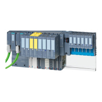
Fig. 3-2 Position of the expansion socket and connector (schematic diagram)
Removing the
connector- and
socket cover
 Loading...